SERVO SELECTION AND DATA SHEETS
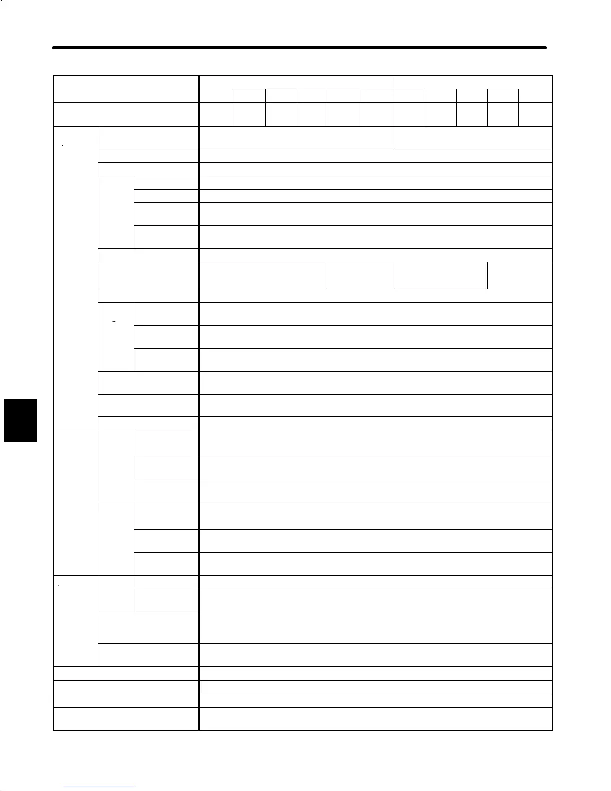
5.3.1 Ratings and Specifications cont.
234
Voltage 200 VAC 100 VAC
Servopack Type DR2- A3AC A5AC 01AC 02AC 04AC 08AC A3BC A5BC 01BC 02BC 03BC
Max. Applicable Motor Capacity
W (HP)
30
(0.04)
50
(0.07)
100
(0.13)
200
(0.27)
400
(0.53)
750
(1.01)
30
(0.04)
50
(0.07)
100
(0.13)
200
(0.27)
300
(0.40)
Basic
Specifica-
Power Supply
(Main/control circuit)
Single-phase 200 to 230 VAC+10% to −15%,
50/60Hz
Single-phase 100 to 115 VAC+10% to
−15%*
2
, 50/60Hz
tions
Control Method Single-phase, full-wave rectification IGBT-PWM (sine-wave driven)
Feedback Incremental encoder 2048 P/R, absolute encoder 1024 P/R
Loca-
Ambient Temp.
0 to +55°C*
3
tion
Storage Temp.
−20 to +85°C
Ambient/Stor-
age Humidity
90% or less (non-condensing)
Vibration/Shock
Resistance
0.5/2G
Structure Rack-mounted*
7
Approx. Mass kg (lb) 2.5 (5.51) 3.7 (8.16) 2.5 (5.51) 3.7 (8.16)
Perfor-
Speed Control Range*
4
1:5000
mance
Speed
Regu-
Load
Regulation
0% to 100%:0.01% max. (at rated speed)
lation*
5
Voltage
Regulation
+10% to -15%: 0.01% max. (at rated speed)
Temperature
Regulation
25¦25°C: ¦0.2% max. (at rated speed)
Frequency
Characteristics
250 Hz (at J
L
=J
M
)
Torque Control
(Repeatability)
¦2.0%
Accel/Decel Time Setting 0to10s
Input
Signal
Speed
Refer-
Rated Refer-
ence Voltage
¦6 VDC (positive motor rotation with positive reference) at rated speed (factory setting)
Variable setting range: ¦2to¦10 VDC at rated torque
Input
Impedance
Approx. 30kΩ
Circuit Time
Constant
Approx. 330µs
Torque
Refer-
Rated Refer-
ence Voltage
¦3 VDC (positive motor rotation with positive reference) at rated speed (factory setting)
Variable setting range: ¦1to¦10 VDC at rated torque
Input
Impedance
Approx. 30kΩ
Circuit Time
Constant
Approx. 330µs
I/O
Posi-
Output Form A-, B-, C-phase line driver*
8
Signals tion
Output
Frequency
Dividing Ratio
(16 to N) /N (N=2048, 1024)*
6
Sequence Input Servo ON, P drive (or motor forward/reverse by torque control, zero-clamp drive reference, or
internal setting speed), forward run stop (P-OT), reverse run stop (N-OT), current limit + selection
(or internal speed selection), current limit − selection (or internal speed selection), alarm reset
Sequence Output Torque limit detection (or speed coincidence) , motor running output (or external brake interlock),
servo ready, servo alarm, 3-bit alarm codes
Dynamic Brake Operated at main power OFF, servo alarm or overtravel.
External Regenerative Unit Required when exceeding the allowable load inertia*
1
Overtravel Dynamic brake stop at P-OT or N-OT or deceleration stop
Protective Functions Overcurrent, overload, overvoltage, overspeed, reference input read error, overrun prevention,
origin error, CPU error, encoder error, fuse blown
5

 Loading...


