SERVO SELECTION AND DATA SHEETS
5.3.1 Ratings and Specifications cont.
236
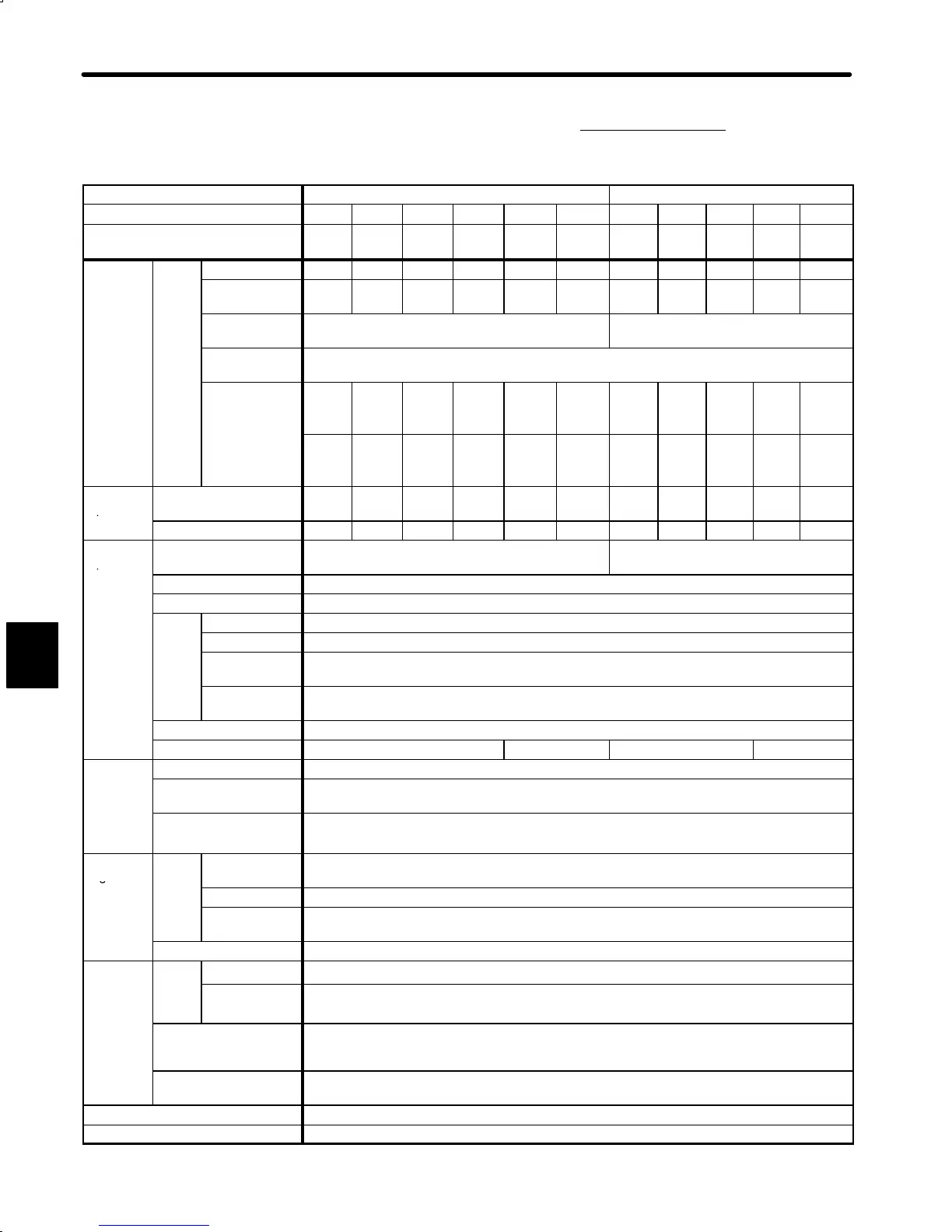
3) Ratings and Specifications of DR2 Servopack for Position
Control
Voltage 200 VAC 100 VAC
Servopack Type DR2- A3AC A5AC 01AC 02AC 04AC 08AC A3BC A5BC 01BC 02BC 03BC
Max. Applicable Motor Capacity
W (HP)
30
(0.04)
50
(0.07)
100
(0.13)
200
(0.27)
400
(0.53)
750
(1.01)
30
(0.04)
50
(0.07)
100
(0.13)
200
(0.27)
300
(0.40)
Combined
Motor
Type
A3Aj A5Aj 01Aj 02Aj 04Aj 08Aj A3Bj A5Bj 01Bj 02Bj 03Bj
Specifica-
tions
Motor Capacity
W (HP)
30
(0.04)
50
(0.07)
100
(0.13)
200
(0.27)
400
(0.53)
750
(1.01)
30
(0.04)
50
(0.07)
100
(0.13)
200
(0.27)
300
(0.40)
Rated/ Max.
Motor Speed
3000/4500 r/min 3000/4500 r/min
Applicable
encoder
Incremental encoder 2048 P/R, absolute encoder 1024 P/R
Allowable Load
Inertia*
1
J
L
kg¡m
2
¢10
−4
2
−3
0.63
(8.80)
0.78
(11.0)
1.20
(17.0)
3.69
(52.2)
5.73
(81.1)
20.1
(284.6)
0.63
(8.80)
0.78
(11.0)
1.20
(17.0)
3.69
(52.2)
5.73
(81.1)
oz¡
n¡s
¢
−
SGM (Upper)/
SGMP (Lower)
− −
1.95
(27.6)
6.27
(88.8)
10.41
(147.4)
18.5
(262.0)
− −
1.95
(27.6)
6.27
(88.8)
10.41
(147.4)
Combined
Specifica-
Continuous Output
Current*
7
0.42 0.6 0.87
(0.89)
2.0 2.6 4.4
(4.1)
0.63 0.90 2.2 2.7 3.7
(4.3)
tions
Max. Output Current 1.3 1.9 2.8 6.0 8.0 13.9 2.0 2.9 7.1 8.4 14.8
Basic
Specifica-
Power Supply
(Main/control circuit)
Single-phase 200 to 230 VAC, +10% to −15%,
50/60 Hz*
2
Single-phase 100 to 115 VAC*
2
, +10% to
−15%, 50/60 Hz
tions
Control Method Single-phase, full-wave rectification IGBT-PWM (sine-wave driven)
Feedback Incremental encoder 2048 P/R, absolute encoder 1024 P/R
Loca-
Ambient Temp.
0to55°C*
3
tion
Storage Temp.
−20°C to +85°C
Ambient/Stor-
age Humidity
90% or less (with no condensation)
Vibration/Shock
Resistance
0.5/2G
Structure Rack-mounted*
5
Approx. Mass kg (lb) 2.5 (5.51) 3.7 (8.16) 2.5 (5.51) 3.7 (8.16)
Perfor-
Bias Setting 0 to 450 r/min. (Setting resolution: 1 r/min.)
mance
Feed Forward
Compensation
0 to 100% (Setting resolution: 1%)
Position Complete Width
Setting
0 to 250 reference units.
Reference unit: minimum unit of position data which moves load
Input
Signal
Refer-
ence
Type
SIGN + PULSE train, 90° phase difference 2-phase pulse, (A-phase+B-phase), CCW pulse+CW
pulse
Pulse
Pulse Form Line driver (+5 V level), open collector (+5 V or +12 V level)
Pulse
Frequency
0 to 450 kpps
Control Signal CLEAR (input pulse form identical to reference pulse)
I/O
Posi-
Output Form A-, B-, C-phase line driver*
6
gna
s t
on
Out-
put
Frequency
Dividing Ratio
(16 to N) /N (N=2048, 1024)*
4
Sequence Input Servo ON, P drive (or motor forward/reverse by internal speed setting), forward run stop (P-OT),
reverse run stop (N-OT), alarm reset, current limit + selection (or internal speed selection), current
limit − selection (or internal speed selection)
Sequence Output Positioning complete, motor running output (or external brake interlock), servo ready, servo alarm,
3-bit alarm codes
Dynamic Brake Operated at main power OFF, servo alarm or overtravel.
External Regenerative Unit Required when exceeding the allowable load inertia
5

 Loading...


