DIFFERENCES BETWEEN DR2 AND DR1, SGDA AND SGD SERVOPACKS
426
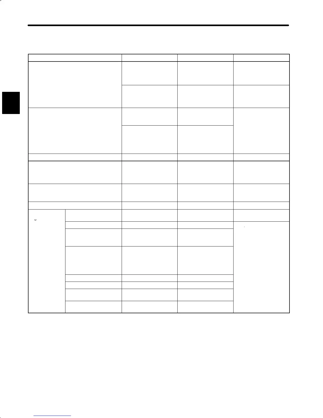
Comparison of the DR2 Servopack with the DR1 Servopack (2)
Item DR2 Servopack DR1 Servopack Remarks
Type
DR2-jjAC
(Semi-closed type)
DR2-jjAC-F
(Full-closed type)
DR1-jjAC
(Incremental type)
DR1-jjAA
(Absolute type)
As for DR2, factory
setting of applicable
motor is SGM
Servomotor.
DR2-jjACP
(Semi-closed type)
DR2-jjACP-F
(Full-closed type)
−
Factory setting of
applicable motor is
SGMP Servomotor.
Outside Dimensions
60W ×250H ×204D
(200V: 30W to 200W)
(100V: 30W to 100W)
60W ×250H ×250D
(200V: 30W to 200W)
(100V: 30W to 100W)
Mounting hole position
is in common with DR2
and DR1.
75W ×250H ×252D
(200V: 400W and
750W)
(100V: 200W and
300W)
75W ×250H ×250D
(200V: 400W and
750W)
(100V: 200W)
Base-mount type Option No
Motor Terminals External terminals in
conformance with
Standard
(PHOENIX CONTACT)
External terminal
(M4 screw)
Encoder Connector 2CN MR-20RMA MR-20RMA Common with DR2 and
DR1. (Different from
SGD type)
Connector 4CN for Full-closed Type MR-8RMA
−
External I/O
Signals
Used Connector MR-50RFA MR-50RFA Common with DR2 and
DR1.
(1CN)
3-pin PL1: PULS pull-up SG: Signal ground
PL1, 2 and 3 are used
5-pin V-REF: Exclusive for
speed reference
input
IN-A: Main input
for pull-up of open
collector input.
9-pin T-REF: Exclusive for
torque
reference
input
IN-B: Auxiliary input
gna
so
er
an
described here are used
in common with DR2
and DR1.
13-pin PL2: SIGN pull-up SG: Signal ground
18-pin PL3: CLR pull-up SG: Signal ground
23-pin +15V: Reference power
supply 30mA
PHC: Phase-C open
collector
24-pin -15V: Reference power
supply 30mA
SG: Signal ground
A

 Loading...


