3.1 Setting User Constants According to Machine Characteristics
61
Cn-18
CLMIF
Forward External
Torque Limit
Unit:
%
Setting
Range: 0 to
Maximum
Torque
Factory
Setting:
100
For Speed/Torque
Control and Position
Control
Cn-19
CLMIR
Reverse External
Torque Limit
Unit:
%
Setting
Range: 0 to
Maximum
Torque
Factory
Setting:
100
For Speed/Torque
Control and Position
Control
Sets a torque limit value when torque is restricted by external contact input.
This function is valid when bit 2 of memory switch Cn-02 is set to 0.
When P-CL (1CN-45) is input Applies torque restriction as specified in Cn-18
When N-CL (1CN-46) is input Applies torque restriction as specified in Cn-19
For torque restriction by analog voltage reference, refer to
3.2.9 Using Torque Restriction
by Analog Voltage Reference
.
•
Using P-CL
and N-CL Signals
This section describes how to use input signals P-CL
and N-CL as torque limit input sig-
nals.
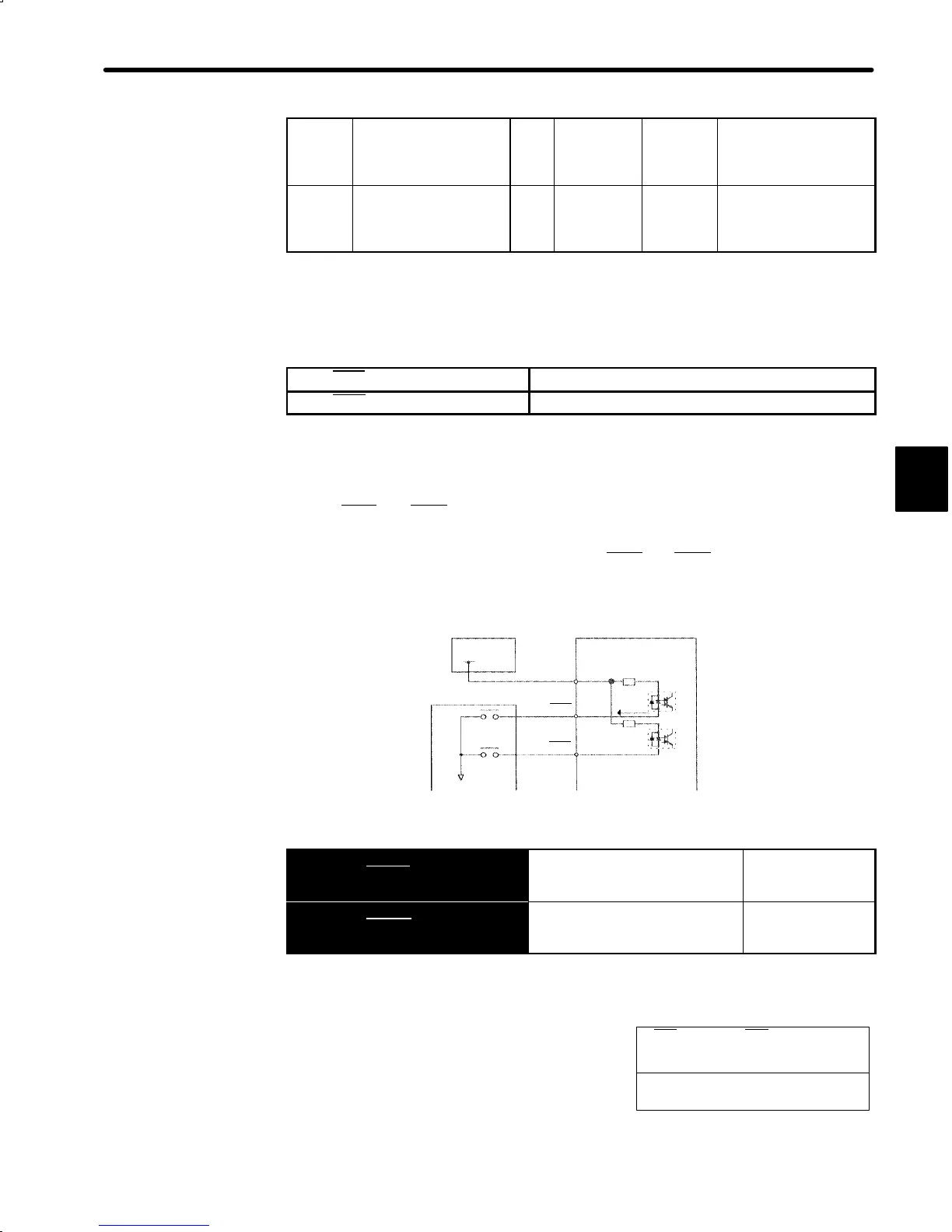
I/O power supply
Servopack
Photocoupler
Host controller
+24VIN
P-CL
N-CL
1CN
-47
-45
-46
4.7kΩ
5mA
→ Input P-CL 1CN-45
Forward External Torque Limit
Input (Speed Selection 1)
For Speed/Torque
Control and
Position Control
→ Input N-CL 1CN-46
Reverse External Torque Limit
Input (Speed Selection 2)
For Speed/Torque
Control and
Position Control
These signals are for forward and reverse exter-
nal torque (current) limit input.
This function is useful in forced stopping.
3
Output Signal for Torque
Restriction Function
• CLT
+ (1CN-25), CLT- (1CN-26)
• Status indication mode bit data
• Monitor mode Un-05 bit 4
• User Constant Setting:
Memory switch Cn-01 bit 4 = 0

 Loading...


