5 Operation
5.3.2 Reference Offset Adjustment
5-24
Note: The automatic adjustment of reference offset (Fn009) cannot be used when a position loop has been formed with a
host controller. Use the manual servo tuning of reference offset described in (2) Manual Adjustment of Reference
Offset (Fn00A).
(2) Manual Adjustment of Reference Offset (Fn00A)
This method adjusts the offset inputting the amount of reference offset directly.
Use the manual servo tuning of reference offset (Fn00A) in the following cases:
• If a position loop is formed with the host controller and the error is zeroed when servolock is stopped.
• To deliberately set the offset to some value.
• To check the offset data set in the automatic adjustment mode of reference offset.
Adjust the reference offset using following steps.
Step
Display after
Operation
Keys Description
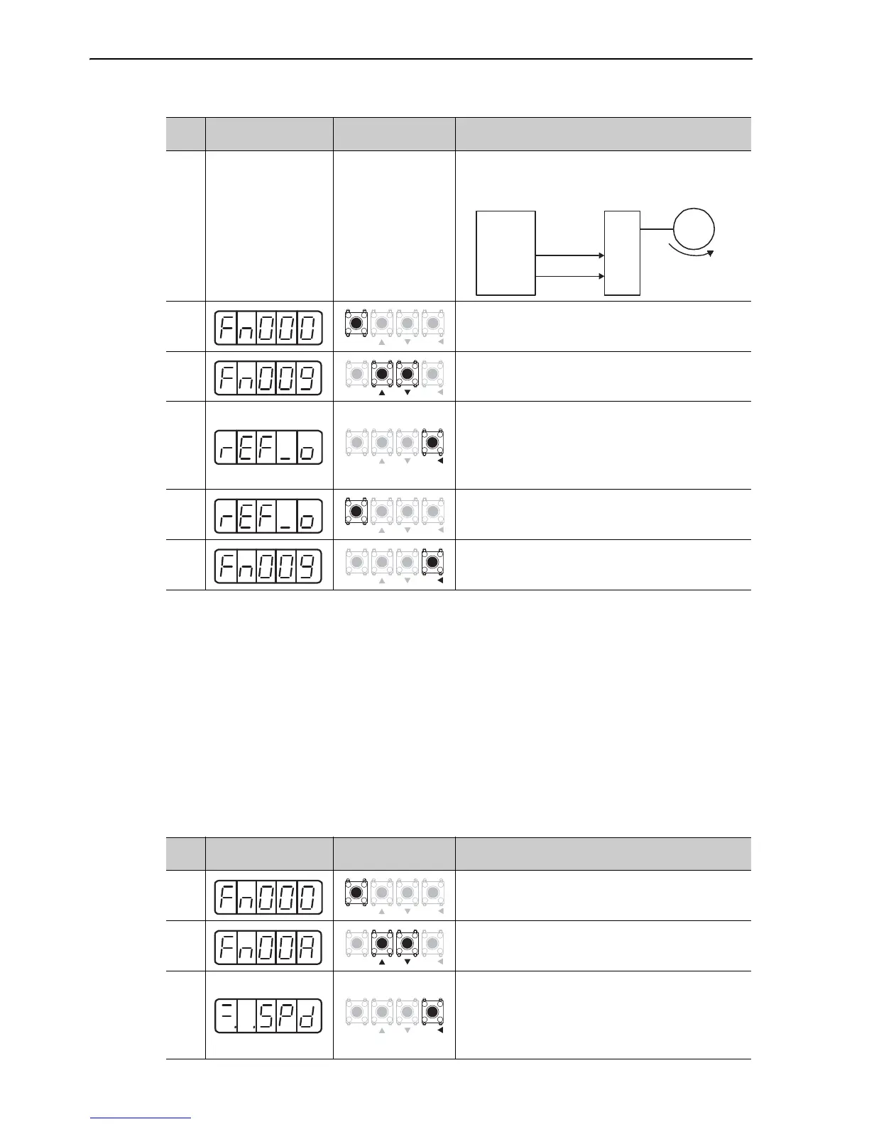
1
Turn OFF the servo ON (/S_ON) signal, and input the 0 V
reference voltage from the host controller or external cir-
cuit.
2
Press the MODE/SET Key to select the utility function
mode.
3 Press the UP or the DOWN Key to select Fn009.
4
Press the DATA/SHIFT Key for approximately one second.
"rEF_o" is displayed.
Note: When "no_OP" blinks for approximately one second,
the write prohibited setting is set in Fn010. Change
the setting in Fn010 and press the key again after
enabling writing. (Refer to 7.12.)
5
Press the MODE/SET Key.
After "donE" blinks for approximately one second, "rEF_o"
is displayed again.
6
Press the DATA/SHIFT Key for approximately one second.
"Fn009" is displayed again.
Step
Display after
Operation
Keys Description
1
Press the MODE/SET Key to select the utility function
mode.
2 Press the UP or the DOWN Key to select Fn00A.
3
Press the DATA/SHIFT Key for approximately one second.
The display shown on the left appears.
Note: When "no_OP" blinks for approximately one second,
the write prohibited setting is set in Fn010. Change
the setting in Fn010 and press the key again after
enabling writing. (Refer to 7.12.)

 Loading...


