5 Operation
5.9.2 Standard Connection Diagram and Setting the Absolute Data Request Signal (SEN)
5-66
5.9.2 Standard Connection Diagram and Setting the Absolute Data Request Signal
(SEN)
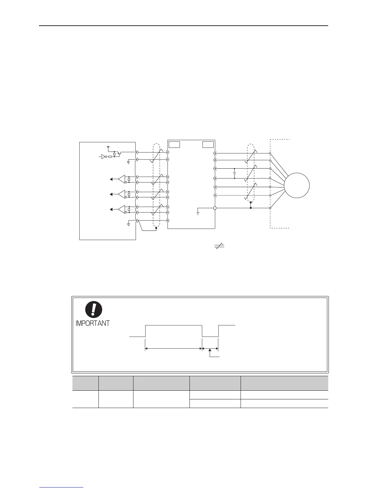
A standard connection example for a servomotor with an absolute encoder, the SERVOPACK, and host con-
troller is shown below.
The absolute data request signal (SEN) must be input for the SERVOPACK to output absolute data. For
details, refer to (2) Setting the Absolute Data Request Signal (SEN).
(1) Standard Connection Diagram
The following diagram shows the standard connections for an absolute encoder.
Note: The connection cable models and wiring pin numbers depend on the servomotor.
(2) Setting the Absolute Data Request Signal (SEN)
For the details of the absolute data reception sequence, refer to 5.9.6 Absolute Encoder Reception Sequence.
Host controller
Battery
SERVOPACK Encoder
Line receiver
Phase A
Phase B
Phase C
: Represents twisted-pair wires.
Shield (shell)
Connector
shell
Applicable line receiver:
Texas Instruments's SN75ALS175 or MC3486
Terminating resistance R: 220 to 470 Ω
∗
Note: Set the SEN signal to low level when the main
circuit power to the SERVOPACK is turned OFF.
R
PG5V
PG0V
BA
PS
/PS
T (+)
BAT ( - -)
PCO
/PCO
PBO
/PBO
PA O
/PAO
SEN
SG
R
R
+5V
7406
0V
4
2
34
33
35
36
19
1
20
CN1
1
2
3
4
6
5
CN2
SG
0V
ENC
∗
∗
+
• Maintain the high level for at least 1.3 seconds when the SEN signal is turned OFF
and then ON, as shown in the figure below.
• SEN Signal cannot be received during Servo ON.
Type Signal Name
Connector
Pin Number
Setting Meaning
Input SEN CN1-4
OFF (low level) Input when power is turned ON
ON (high level) Input at absolute data request

 Loading...


