3 Wiring and Connection
3.1.2 SERVOPACK Main Circuit Wire Size
3-4
3.1.2 SERVOPACK Main Circuit Wire Size
This section describes the SERVOPACK Main Circuit Wire Size.
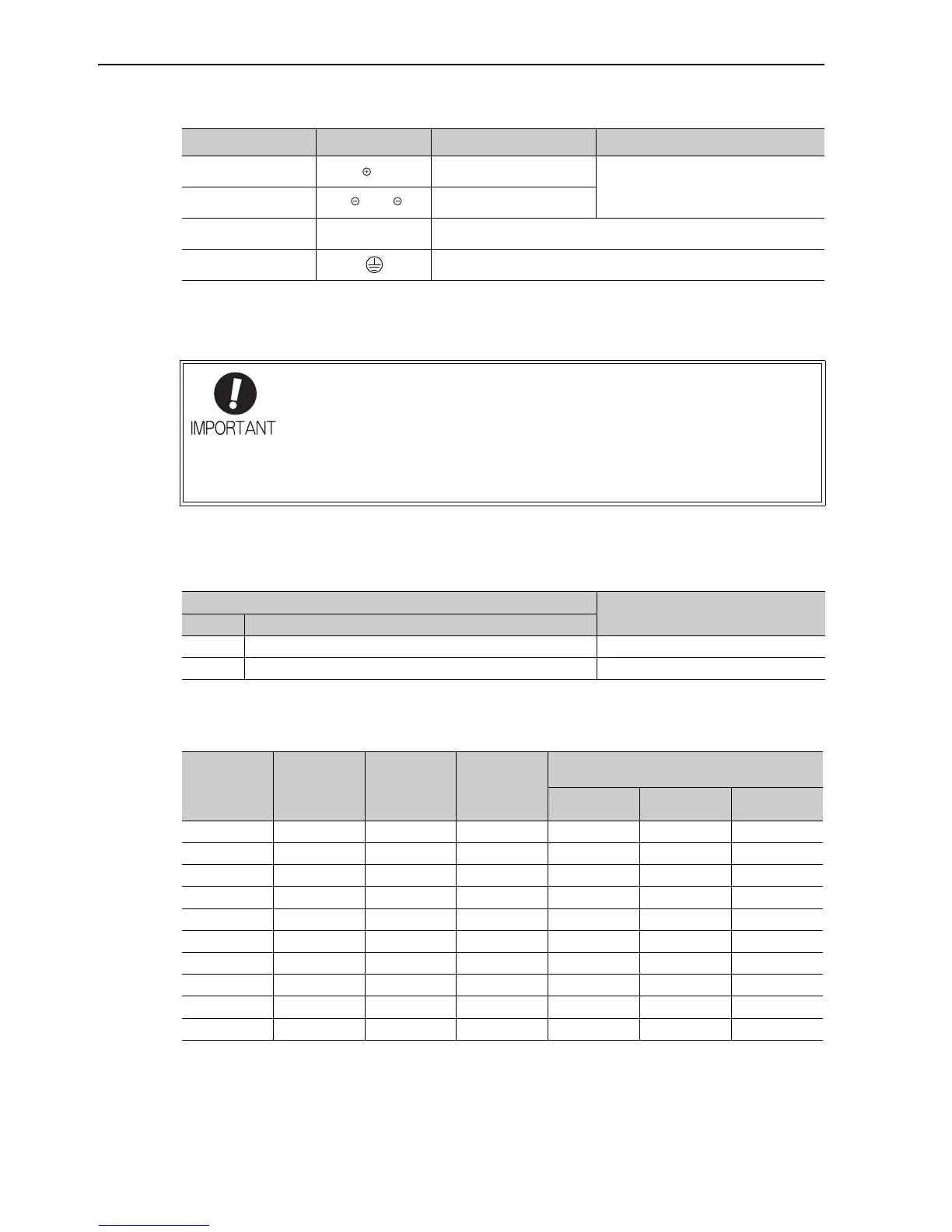
(1) Wire Types
Use the following type of wire for main circuit.
The following table shows the wire sizes and allowable currents for three wires. Use wires with specifications equal to or
less than those shown in the table.
• 600 V Second Class Vinyl Insulated Cable (HIV)
Note: The values in the table are for reference only.
Main circuit plus
terminal
B1/ or B1
A
D
Use when DC power supply input is used.
Main circuit minus
terminal
2 or
A
D
Servomotor
connection terminals
U, V, W Use for connecting to the servomotor.
Ground terminals
(× 2)
Use for connecting the power supply ground terminal and servomotor
ground terminal.
Name Terminal Symbols Model SGDV-
Description
1. Wire sizes are selected for three cables per bundle at 40°C surrounding air tempera-
ture with the rated current.
2. Use a wire with a minimum withstand voltage of 600 V for the main circuit.
3. If cables are bundled in PVC or metal ducts, take into account the reduction of the
allowable current.
4. Use a heat-resistant wire under high surrounding air or panel temperatures, where
polyvinyl chloride insulated wires will rapidly deteriorate.
Cable Type
Allowable Conductor Temperature °C
Symbol Name
IV 600 V polyvinyl chloride insulated wire 60
HIV 600 V grade heat-resistant polyvinyl chloride insulated wire 75
AWG Size
Nominal
Cross Section
Diameter
(mm
2
)
Configuration
(Number of
Wires/mm
2
)
Conductive
Resistance
(Ω/km)
Allowable Current at Surrounding Air
Temperature (A)
30°C 40°C 50°C
20 0.5 19/0.18 39.5 6.6 5.6 4.5
19 0.75 30/0.18 26.0 8.8 7.0 5.5
18 0.9 37/0.18 24.4 9.0 7.7 6.0
16 1.25 50/0.18 15.6 12.0 11.0 8.5
14 2.0 7/0.6 9.53 23 20 16
12 3.5 7/0.8 5.41 33 29 24
10 5.5 7/1.0 3.47 43 38 31
8 8.0 7/1.2 2.41 55 49 40
6 14.0 7/1.6 1.35 79 70 57
4 22.0 7/2.0 0.85 91 81 66

 Loading...


