3 Wiring and Connection
3.2.1 I/O Signal (CN1) Names and Functions
3-16
3.2 I/O Signal Connections
This section describes the names and functions of I/O signals (CN1). Also terminal layout and connection
examples by control method are shown.
3.2.1 I/O Signal (CN1) Names and Functions
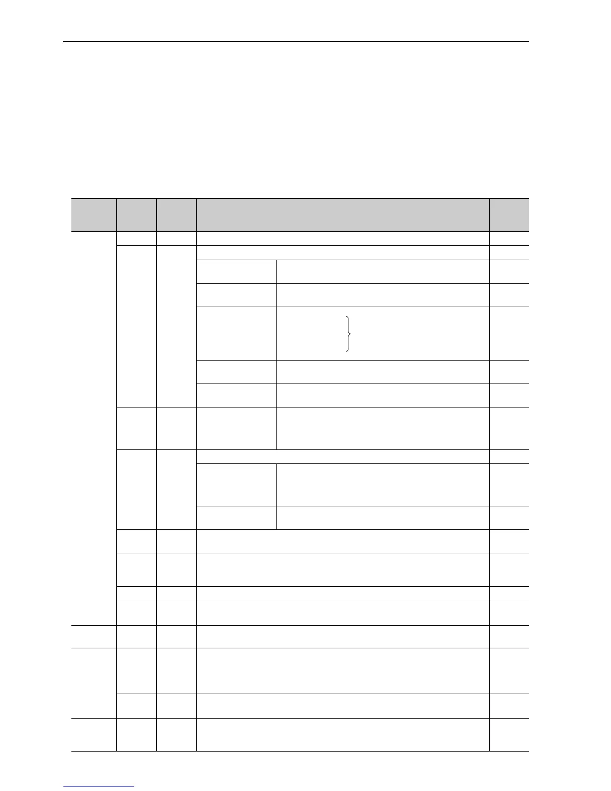
The following table shows the names and functions of I/O signals (CN1).
(1) Input Signals
Control
Method
Signal
Name
Pin No. Function
Refer-
ence
Section
Common
/S-ON 40 Servo ON/OFF: Turns ON/OFF the servomotor. 5.2.1
/P-CON 41
Function selected by parameter. −
Proportional control
reference
Switches the speed control loop from PI (proportional/
integral) to P (proportional) control when ON.
6.9.4
Direction reference
For the internal set speed selection: Switches the rotation
direction.
5.6.1
Control switching 5.7.1
Zero-clamp reference
Speed control with zero-clamp function: Reference
speed is zero when ON.
5.3.5
Reference pulse
block
Position control with reference pulse stop: Stops reference
pulse input when ON.
5.4.7
P-OT
N-OT
42
43
Forward run
prohibited,
Reverse run
prohibited
Overtravel prohibited: Stops servomotor when movable part
travels beyond the allowable range of motion.
5.2.3
/P-CL
/N-CL
45
46
Function selected by parameter. 5.10.1
Forward external
torque limit,
Reverse external
torque limit
Activates/deactivates external torque limit function.
5.8.2
5.8.4
Internal speed
switching
With internal reference speed selected: Switches the
internal speed settings.
5.6.1
/ALM-
RST
44 Alarm reset: Releases the servo alarm state. −
+24VIN 47
Control power supply input for sequence signals: The 24 VDC power supply is not
included.
Allowable voltage fluctuation range: 11 to 25 V
3.4.2
SEN 4 (2) Initial data request signal when using an absolute encoder. 5.9.2
BAT (+)
BAT (-)
21
22
Connecting pin for the absolute encoder backup battery.
Do not connect when the encoder cable for the battery case is used.
3.5.1
5.9.2
Speed V-REF 5 (6) Inputs speed reference. Input voltage range: ± 12 V max.
5.3.1
5.5.4
Position
PULS
/ PULS
SIGN
/SIGN
7
8
11
12
Input pulse modes: Set one of them.
• Sign + pulse string
• CCW/CW pulse
• Two-phase pulse (90° phase differential)
5.4.1
CLR
/CL
R
15
14
Position error pulse clear: Clears position error pulse during position control. 5.4.2
Tor qu e T-REF 9 (10) Inputs torque reference. Input voltage range: ± 12 V max.
5.5.1
5.8.3
5.8.5
Position
↔
speed
Position
↔
torque
Torque
↔
speed
Enables control switching.