3 Wiring and Connection
3.2.6 Example of I/O Signal Connections in Torque Control
3-22
3.2.6 Example of I/O Signal Connections in Torque Control
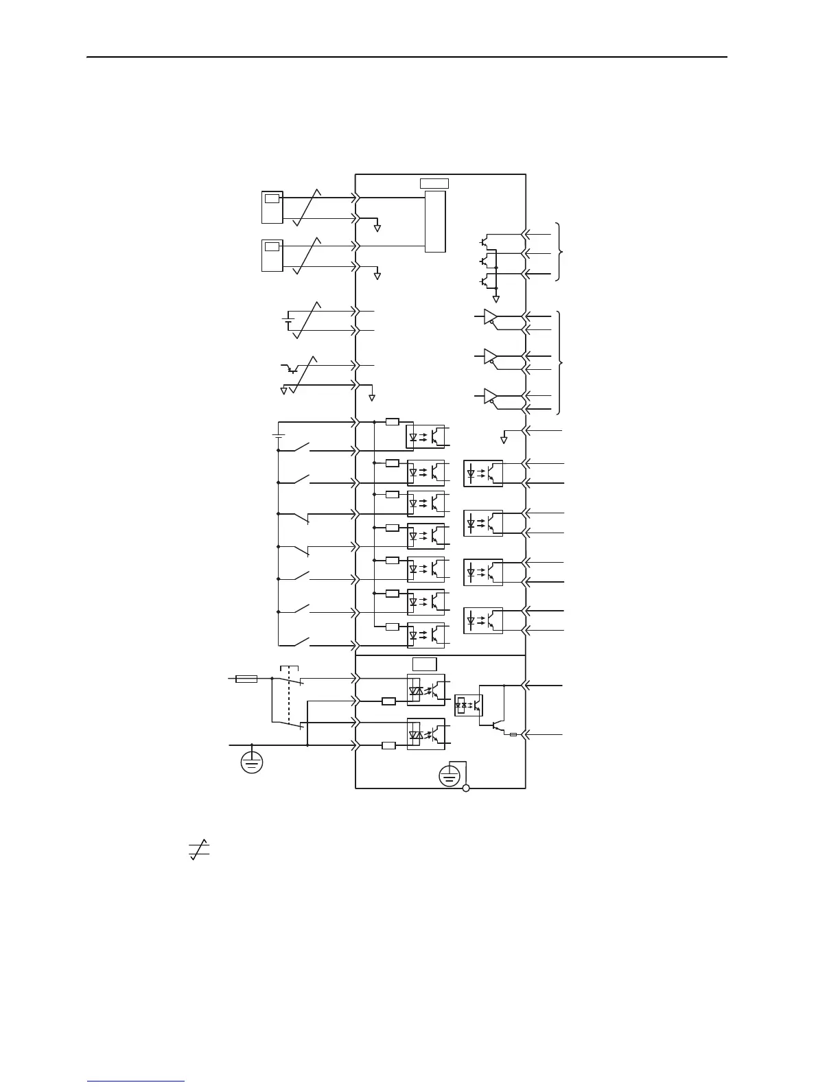
Connection example in torque control mode is as shown below.
∗1. represents twisted-pair wires.
∗2. Connect when using an absolute encoder. When the encoder cable for the battery case is connected, do not connect a
backup battery.
∗3. Enabled by the parameter setting.
∗4. The 24 VDC power supply is not included. Use a power supply with a double-shielded enclosure.
∗5. To turn the servomotor power ON, a safety device must be connected and the wiring to activate the safety function
must be done. When not using the safety function, use the SERVOPACK with the plug (JZSP-CVH05-E, provided as
an accessory) inserted into the CN8.

 Loading...


