5.9.6 Absolute Encoder Reception Sequence
The sequence in which the SERVOPACK receives outputs from the absolute encoder and transmits them to
host controller is shown below.
(1) Outline of Absolute Signals
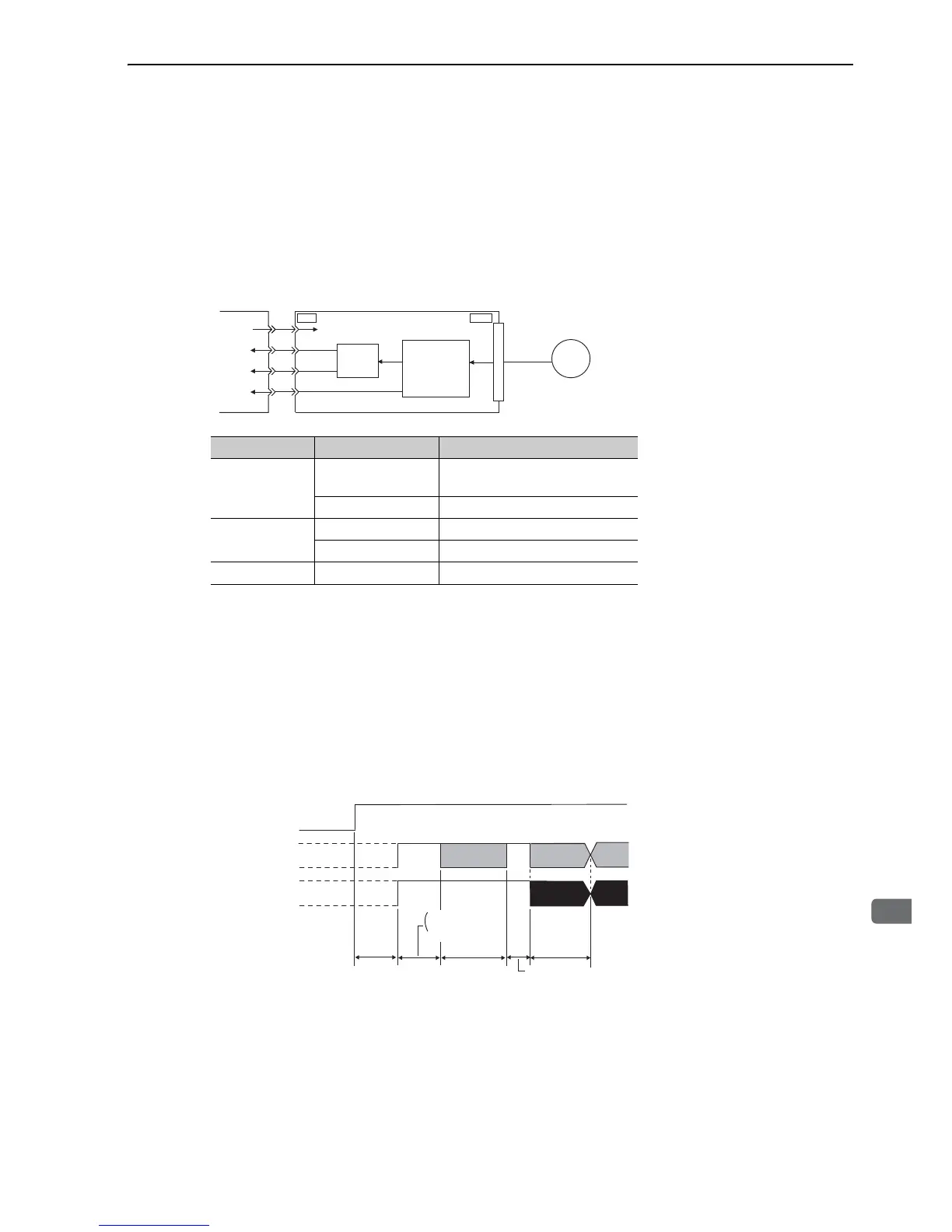
The serial data, pulses, etc., of the absolute encoder that are output from the SERVOPACK are output from the
PAO, PBO, and PCO signals as shown below.
Note: When host controller receives the data of absolute encoder, do not perform counter reset using the output of PCO
signal.
(2) Absolute Encoder Transmission Sequence and Contents
Absolute Encoder Transmission Sequence
1. Set the SEN signal at ON (high level).
2. After 100 ms, set the system to serial data reception-waiting-state. Clear the incremental pulse up/down
counter to zero.
3. Receive eight bytes of serial data.
4. The system enters a normal incremental operation state about 400 ms after the last serial data is received.
∗ In case of reverse rotation mode (Pn000.0 = 1), the output polarity for PBO signal inverts.
Rotational serial data:
Indicates how many turns the motor shaft has made from the reference position (position at setup).
Signal Name Status Contents
PAO
At initialization
Rotational serial data
Initial incremental pulses
Normal time Incremental pulses
PBO
At initialization Initial incremental pulses
Normal time Incremental pulses
PCO Always Origin pulses
CN31
Serial
data
External
encoder
CN1
Serial data→
pulse conversion
Host
controller
SERVOPACK with option module for
fully-closed loop control
SEN
PAO
PBO
PCO
Dividing
circuit
(Pn212)

 Loading...


