6 Adjustments
6.1.3 Monitoring Analog Signals
6-6
6.1.3 Monitoring Analog Signals
Check the operating status and signal waveform when adjusting the servo gain. Connect a measuring instru-
ment, such as a memory recorder, to connector CN5 on the SERVOPACK to monitor analog signal waveform.
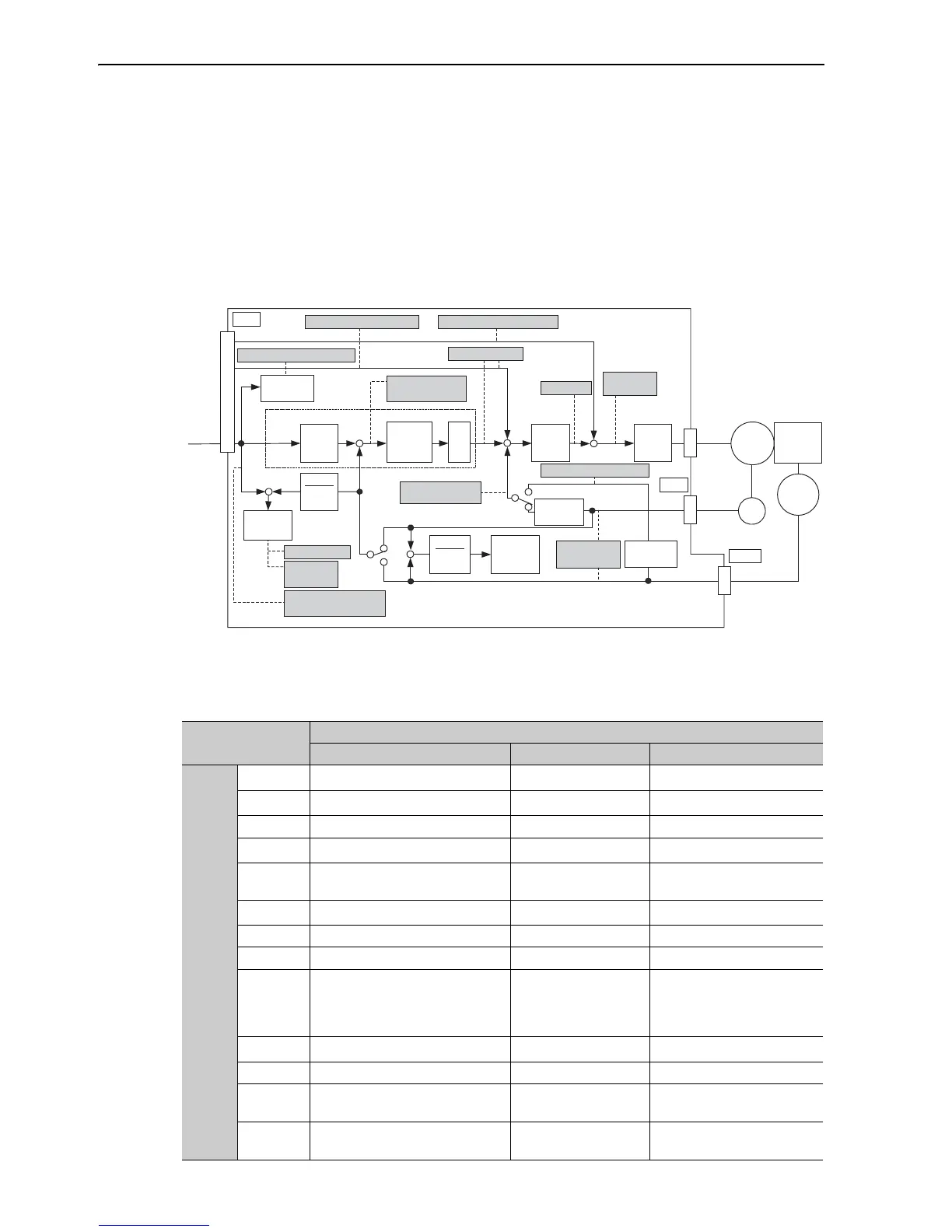
The settings and parameters for monitoring analog signals are described in the following sections.
(1) Monitor Signal
The following diagram shows the analog monitor output at position control.
The following signals can be monitored by selecting functions of parameters Pn006 and Pn007.
Pn006 is used for analog monitor 1 and Pn007 is used for analog monitor 2.
Parameter
Description
Monitor Signal Measurement Gain Remarks
Pn006
Pn007
n.00 Motor speed
1 V/1000 min
-1 *
Pn007 Factory Setting
n.01 Speed reference
1 V/1000 min
-1 *
−
n.02 Torque reference 1 V/100% rated torque Pn006 Factory Setting
n.03
Position error
0.05 V/reference unit 0 V at speed/torque control
n.04
Position amplifier error
0.05 V/encoder pulse
unit
Position error after electronic
gear conversion
n.05 Position reference speed
1 V/1000 min
-1 *
−
n.06 Reserved −−
n.07 Motor-load position error 0.01 V/reference unit −
n.08 Positioning completed
Positioning completed:
5 V
Positioning not com-
pleted: 0 V
−
n.09 Speed feedforward
1 V/1000 min
-1 *
−
n.0A Torque feedforward 1 V/100% rated torque −
n.0B Active gain
1 st gain: 1 V
2 nd gain: 2 V
−
n.0C Completion of position reference
Completed: 5 V
Not completed: 0 V
−

 Loading...


