EasyManua.ls Logo

YASKAWA SGMJV

YASKAWA SGMJV
400 pages
To Next Page IconTo Next Page
To Previous Page IconTo Previous Page
Loading...
3.1 Main Circuit Wiring
3-15
3
Wiring and Connection
3.1.7 Precautions When Using More Than One SERVOPACK
This section shows an example of the wiring when more than one SERVOPACK is used and the precautions.
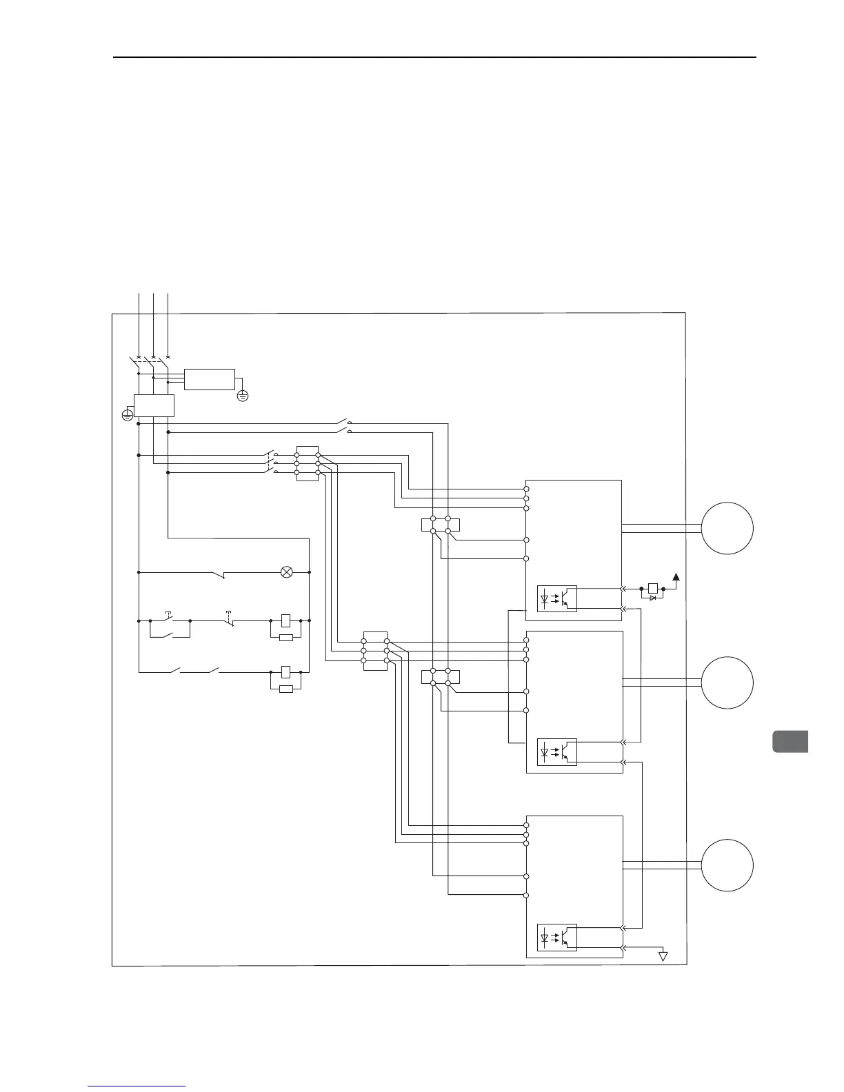
(1) Wiring Example
Connect the alarm output (ALM) terminals for the three SERVOPACKs in series to enable alarm detection
relay 1RY to operate.
When the alarm occurs, the ALM output signal transistor is turned OFF.
(2) Precautions
Multiple servos can share a single molded-case circuit breaker (1QF) or noise filter. Always select a QF or
noise filter that has enough capacity for the total power capacity (load conditions) of those servos.
L1
L2
L3
L1C
L2C
SERVOPACK
Servomotor
Servomotor
M
Servomotor
M
M
Relay
terminal
Relay
terminal
Relay
terminal
1QF:
1FIL:
1KM: Magnetic contactor
(for control power supply)
2KM:
(for main power supply)
1Ry:
1PL:
1SA:
2SA:
3SA:
1D:
Molded-case circuit breaker
Noise filter
Relay
Magnetic contactor
Indicator lamp
Surge absorber
1Ry
+24V
CN1
CN1
CN1
31
ALM+
32ALM
-
0V
L1
L2
L3
31
ALM+
32
ALM
-
L1
L2
L3
L1C
ID
31
ALM+
32
ALM
-
L2C
L1C
L2C
SERVOPACK
SERVOPACK
Surge absorber
Surge absorber
Flywheel diode
supply ON
1KM
RS T
1QF
2KM
Power supply
1FIL
Relay
terminal
3SA
1KM
(For servo alarm
display)
1Ry
1PL
1KM
2KM
1SA
Servo power
supply OFF
Servo power
1Ry1KM
2SA

Table of Contents

Related product manuals