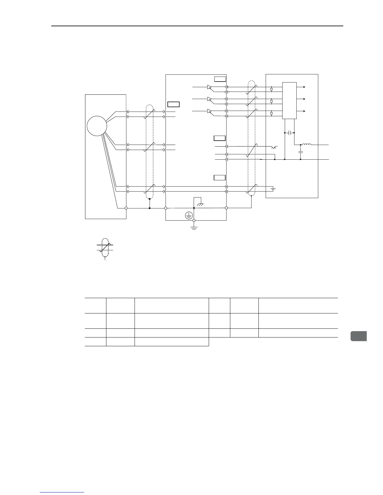
(2) Absolute Encoders
∗1. The pin numbers for the connector wiring differ depending on the servomotors.
∗2. : represents twisted-pair wires.
∗3. When using an absolute encoder, install a battery in a battery case (JZSP-BA01)
of encoder cable, or install a battery on the host controller side to supply power.
∗4. Applicable line receiver: SN75ALS175 manufactured by Texas Instruments or MC3486, or the equivalent.
3.5.2 CN2 Encoder Connector Terminal Layout
/PCO
3
4
4
2
SG
SEN
21
22
BAT
BAT
+
-
CN2
33
34
35
36
19
20
CN1
SG
1
PA
O
/P
AO
PBO
/PBO
PCO
Light blue
White/
light blue
Absolute encoder
Red
Black
Shield wire
Orange
White/
orange
(Shell)
SERVOPACK
Phase A
Phase B
Phase C
Connector
shell
Connector
shell
CN1
CN1
∗2
∗4
∗3
∗2
∗1
0V
0V
+5V
+5V
+5V
Phase
A
Phase
B
Phase
C
Line receiver
Host controller
Choke
coil
Smoothing
capacitor
R (terminal resistance): 220 to 470 Ω
C (Decoupling Capacitor)㧦
0.1 μF
11
5
3
2
1
R
6
7
10
9
816
C
+
-
R
R
+
-
Battery
5
6
1
2
Output line-driver SN75ALS174
or the equivalent.
PS
/PS
PG5V
PG0V
BAT(+)
BAT(-)
ENC
1PG 5 V
Encoder power supply
+5 V
2PG 0 V
Encoder power supply
0 V
3BAT (+)
Battery (+)
(For an absolute encoder)
4BAT (-)
Battery (-)
(For an absolute encoder)
5PS Serial encoder signal input (+) 6/PS Serial encoder signal input (-)
SHELL Shield -

 Loading...


