Set the level to a value that satisfies these equations, and no alarm will be generated during normal operation.
The servomotor will be stopped, however, if the servomotor runs unpredictably after a reference is input or if
a position error in accordance with the value set in Pn520 occurs. At the end of the equation, a coefficient is
shown as
"× (1.2 to 2)." This coefficient is used to add a margin that prevents a faulty alarm from occurring in
actual operation of the servomotor.
If the servomotor’s maximum number of rotations is 6000 min
-1
and Pn102 equals 40 with an encoder resolu-
tion of 20-bit (1048576), the setting of Pn520 is calculated as shown with the following equation.
If the acceleration/deceleration of the position reference exceeds the capacity of the servomotor, the servomo-
tor cannot perform at the requested speed, and the allowable level for position error will be increased as not to
satisfy these equations. If so, lower the level of the acceleration/deceleration for the position reference so that
the servomotor can perform at the requested speed or raise the allowable level of the position errors.
Related Parameter
Related Alarm
(4) Vibration Detection Function
Set the vibration detection function to an appropriate value. For details on how to set the vibration detection
function, refer to 7.16 Vibration Detection Level Initialization (Fn01B)
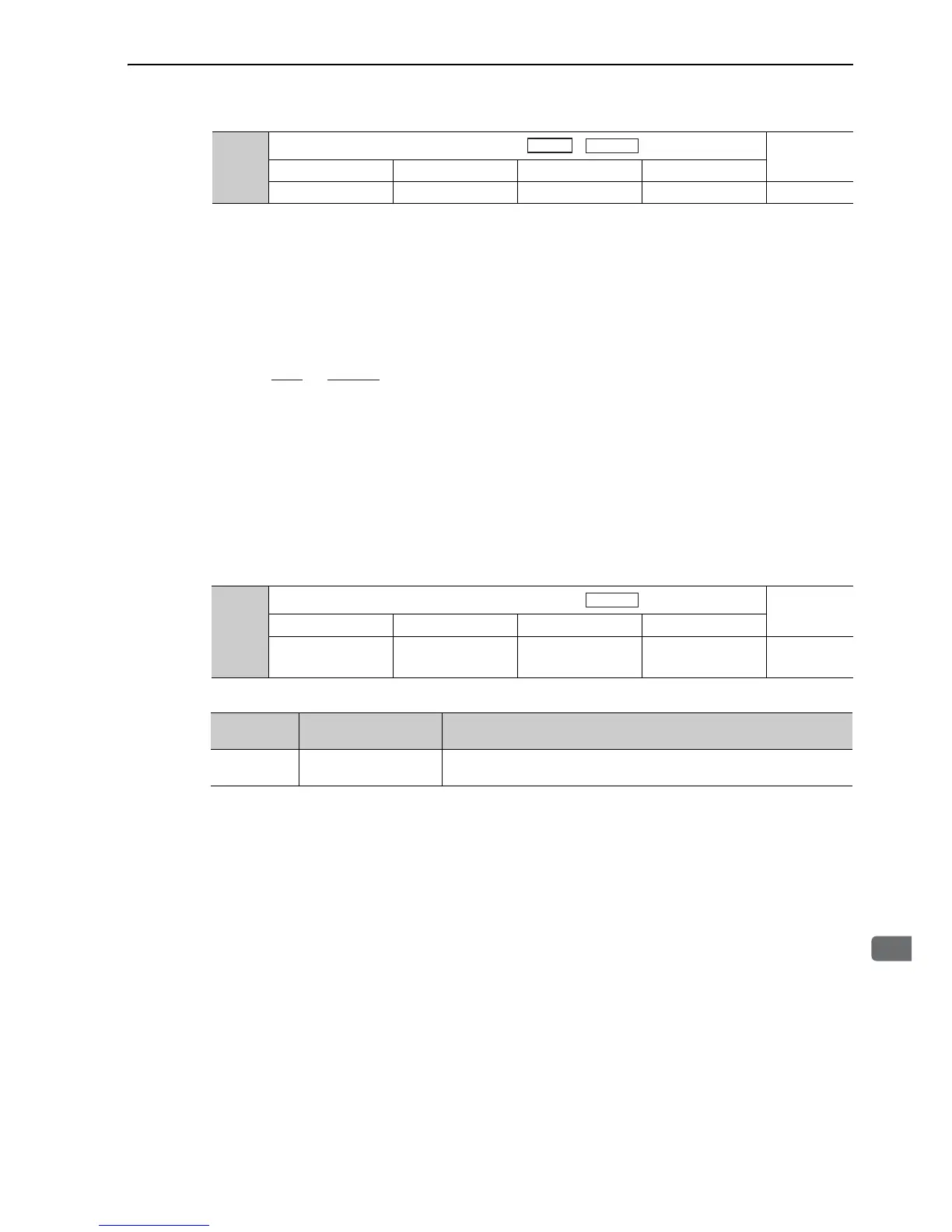
Pn102
Position Loop Gain
Classification
Setting Range Setting Unit Factory Setting When Enabled
10 to 20000 0.1 /s 400 Immediately Tuning
Speed Position
Pn520
Excessive Position Error Alarm Level
Classification
Setting Range Setting Unit Factory Setting When Enabled
1 to 1073741823
(2
30
-1)
1 reference unit 5242880 Immediately Setup
Alarm
Display
Alarm Name Alarm Contents
A.d00
Position Error Pulse
Overflow
Position error pulses exceeded parameter Pn520.
Position

 Loading...


