Notes:
• Monitoring the speed response waveform and position error waveform is required for adjustment.
• If I-P control is selected for speed loop control, the mode switching function will be disabled.
(1) Related Parameters
Select the conditions to switch modes (P or PI control switching) by using the following parameters.
Parameters to set the detection point
Mode switch functions according to the detection point are as follows.
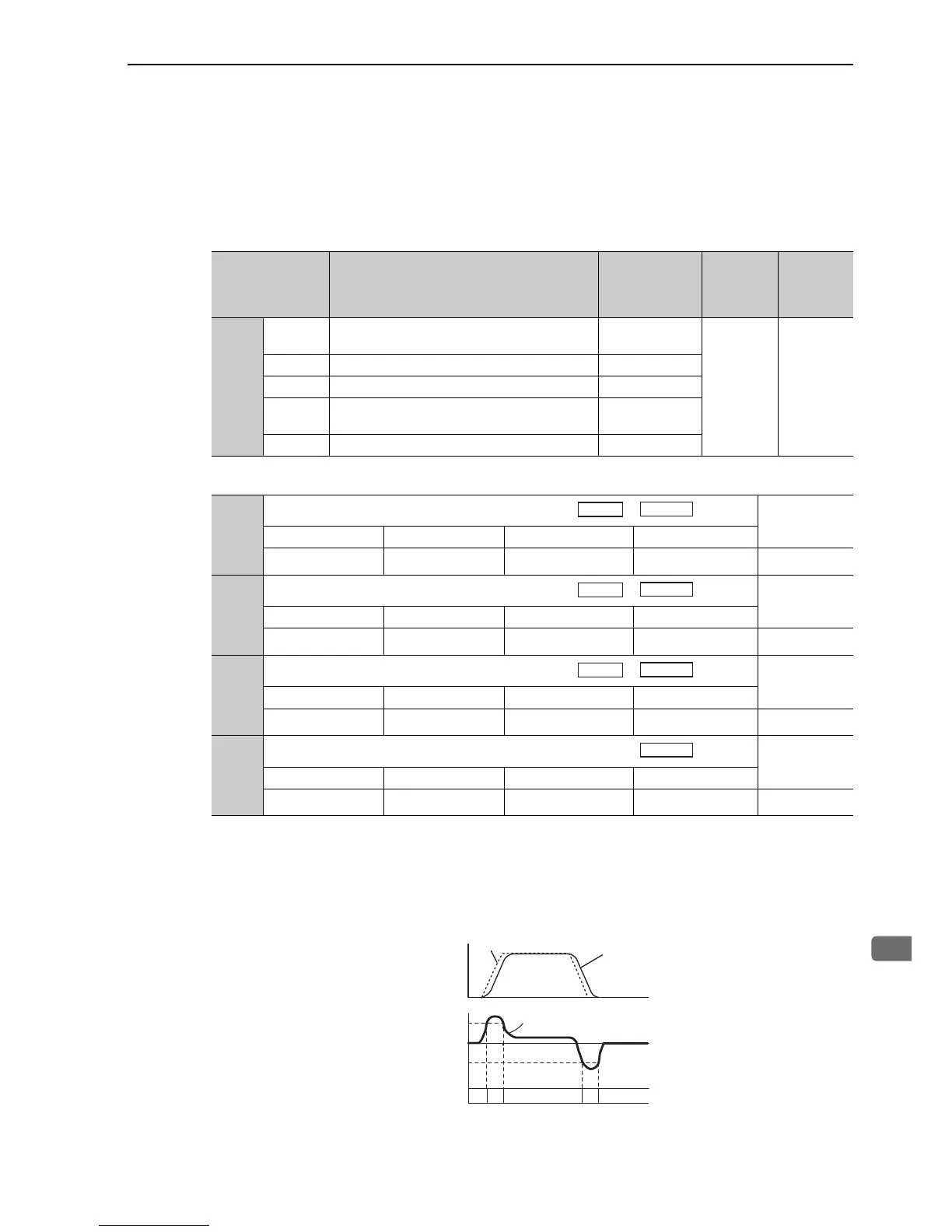
Using the Torque Reference Level to Switch Modes (Factory Setting)
With this setting, the speed loop is switched to P control when the value of torque reference input exceeds the
torque set in Pn10C. The factory setting for the torque reference detection point is 200% of the rated torque.
Parameter
Mode Switch
Selection
Parameter
Containing
Detection Point
Setting
When
Enabled
Classificati
on
Pn10B
n.0
Uses a torque reference level for detection point.
[Factory setting]
Pn10C
Immediately Setup
n.1 Uses a speed reference level for detection point. Pn10D
n.2 Uses an acceleration level for detection point. Pn10E
n.3
Uses an position error pulse level for detection
point.
Pn10F
n.4 Does not use mode switch function. −
Pn10C
Mode Switch (Torque Reference)
Classification
Setting Range Setting Unit Factory Setting When Enabled
0 to 800 1 % 200 Immediately
Tuning
Pn10D
Mode Switch (Speed Reference)
Classification
Setting Range Setting Unit Factory Setting When Enabled
0 to 10000
1 min
-1
0 Immediately
Tuning
Pn10E
Mode Switch (Acceleration)
Classification
Setting Range Setting Unit Factory Setting When Enabled
0 to 30000
1 min
-1
/s
0 Immediately
Tuning
Pn10F
Mode Switch (Position Error)
Classification
Setting Range Setting Unit Factory Setting When Enabled
0 to 10000 1 reference unit 0 Immediately
Tuning

 Loading...


