(2) Absolute Encoder Transmission Sequence and Contents
Absolute Encoder Transmission Sequence
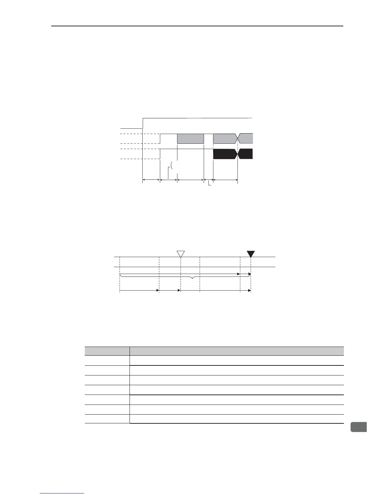
1. Set the SEN signal at ON (high level).
2. After 100 ms, set the system to serial data reception-waiting-state. Clear the incremental pulse up/down
counter to zero.
3. Receive eight bytes of serial data.
4. The system enters a normal incremental operation state about 400 ms after the last serial data is received.
Serial data:
The current position pulses divided by Pn281 are output in serial data.
One serial data is a value equivalent to 1048576 pulses.
Initial incremental pulses:
The current position pulses divided by Pn281 are output in pulses. The number of output pulses is between 0
to 1048576, and the output speed is approximately 1.48 µs per pulse.
Final absolute data P
M
is calculated by following formula.
P
E
=M
O
× R+P
O
P
M
=P
E
–M
S
×R–P
S
Note: When host controller receives the data of absolute encoder, do not perform counter reset using the output of PCO
signal.
Signal Meaning
P
E
Current position of external encoder
M
O
Serial data of current position
P
O
Number of initial incremental pulses of current position
M
S
Serial data of reference position
P
S
Number of initial incremental pulses of reference position
P
U
Current value required for the user’s system
R 1048576

 Loading...


