3 Wiring and Connection
3.1.3 Typical Main Circuit Wiring Examples
3-6
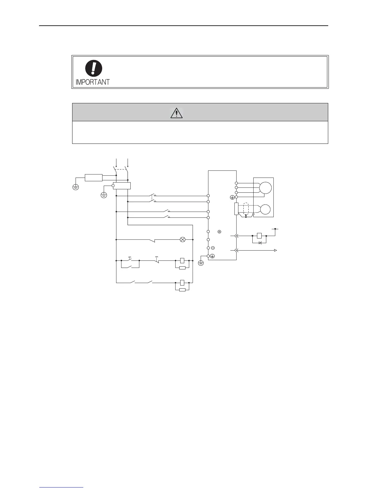
The typical main circuit wiring examples are shown below.
Single-phase 100 V, SGDV-F (SGDV-R70F, R90F, 2R1F, 2R8F)
• When turning ON the control power supply and the main circuit power supply, turn
them ON at the same time or after the control power supply. When turning OFF the
power supplies, first turn the power for the main circuit OFF and then turn OFF the
control power supply.
WARNING
• Do not touch the power terminals after turning OFF the power. High voltage may still remain in the SER-
VOPACK. When the voltage is discharged, the charge indicator will turn OFF. Make sure the charge indi-
cator is OFF before starting wiring or inspections.
1PL: Indicator lamp
1SA: Surge absorber
2SA: Surge absorber
3SA: Surge absorber
1D: Flywheel diode
1QF: Molded-case circuit breaker
1FIL: Noise filter
1KM: Magnetic contactor (for control power supply)
2KM: Magnetic contactor (for main power supply)
1Ry: Relay
L1
ENC
SERVOPACK
SGDV-F
U
V
W
M
0 V
1Ry
ALM+
ALM−
31
32
1D
2KM
1KM
B2
L2
CN1
1QF
RT
1FIL
+24V
B1/
3SA
(For servo
alarm display)
1Ry
1PL
supply ON
1KM
2KM
1SA
Servo power
supply OFF
Servo power
1KM
1Ry1KM
2SA
L1C
L2C

 Loading...


