• Auto-Tuning is not possible with permanent magnet motors.
• To cancel Auto-Tuning, press the STOP key on the LED operator.
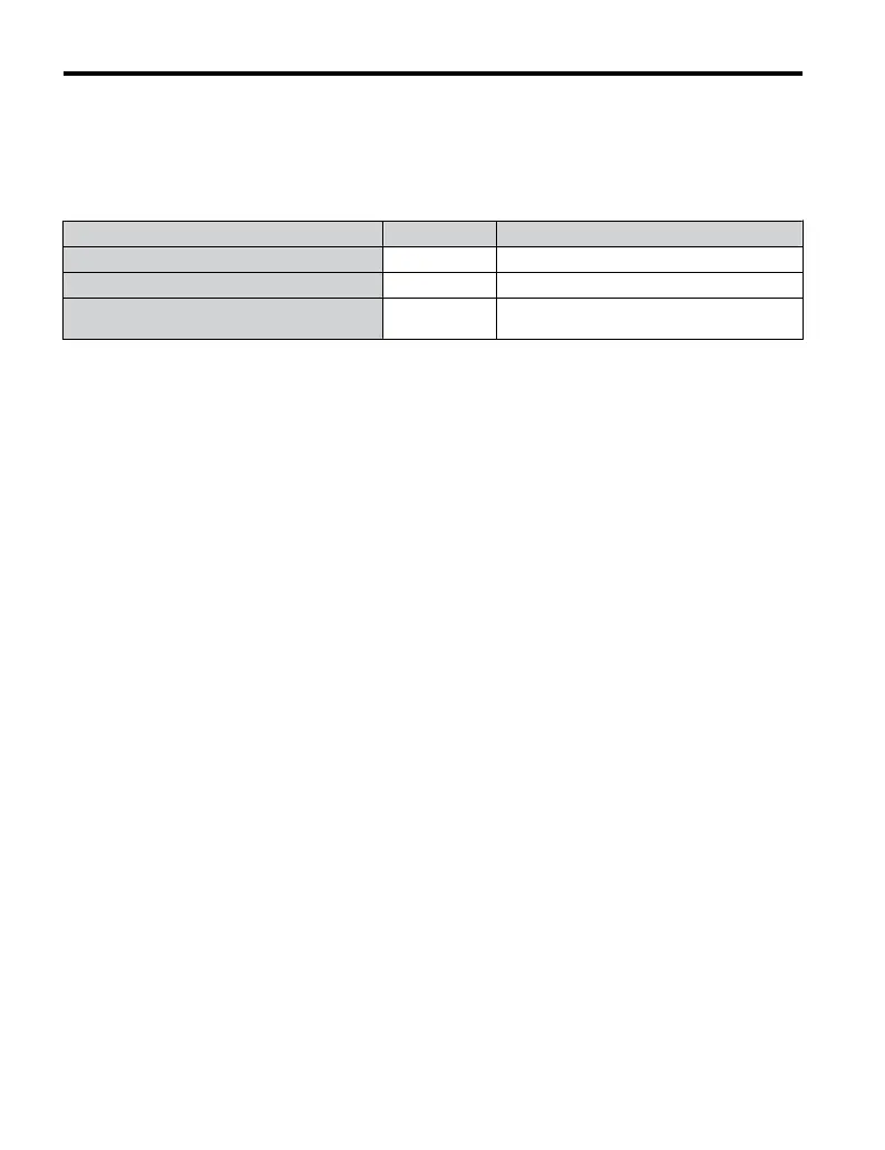
• Table 4.19 describes digital input and output terminal status during Auto-Tuning.
Table 4.19 Digital Input and Output Operation During Auto-Tuning
Auto-Tuning Type Digital Input Digital Output
Rotational Auto-Tuning for V/f Control Not available Functions the same as during normal operation
Rotational Auto-Tuning for OLV Control Not available Functions the same as during normal operation
Stationary Auto-Tuning for Line-to-Line
Resistance
Not available Maintains the status at the start of Auto-Tuning
WARNING! Sudden Movement Hazard. Do not release the mechanical brake during stationary Auto-Tuning.
Inadvertent brake release may cause damage to equipment or injury to personnel. Ensure that the mechanical
brake release circuit is not controlled by the drive multi-function digital outputs.
Note: It is recommended that Rotational Auto-Tuning is performed with the load disconnected. Failure to
comply could result in improper drive operation. If Rotational Auto-Tuning is performed for a motor
coupled to a load, the motor constants will be inaccurate and the motor may exhibit abnormal operation.
Disconnect or decouple the motor from the load.
n
Notes on Rotational Auto-Tuning
• For optimal performance, Auto-Tuning should only be done with the motor uncoupled from
the load for applications requiring high performance over a wide speed range.
• If motor and load can not be uncoupled, the load should be lower than 30% of the rated
load. Performing Rotational Auto-Tuning with a higher load will set motor parameters
incorrectly, and can cause irregular motor rotation.
• Ensure the motor-mounted brake is fully released if installed.
• Connected machinery should be allowed to rotate the motor.
n
Notes on Stationary Auto-Tuning for Terminal Resistance Only
• If the motor cable lead length has been significantly modified after Auto-Tuning has already
been performed, perform Stationary Auto-Tuning with the new cables.
• Perform when using motor cables longer than 50 m with V/f Control.
WARNING! Electrical Shock Hazard. When executing stationary Auto-Tuning for line-to-line resistance only,
the motor does not rotate, however, power is applied. Do not touch the motor until Auto-Tuning is completed.
Failure to comply may result in injury from electrical shock.
4.7 Auto-Tuning
114
YASKAWA ELECTRIC TOEP C710606 47A YASKAWA AC Drive – V1000 Quick Start Guide

 Loading...


