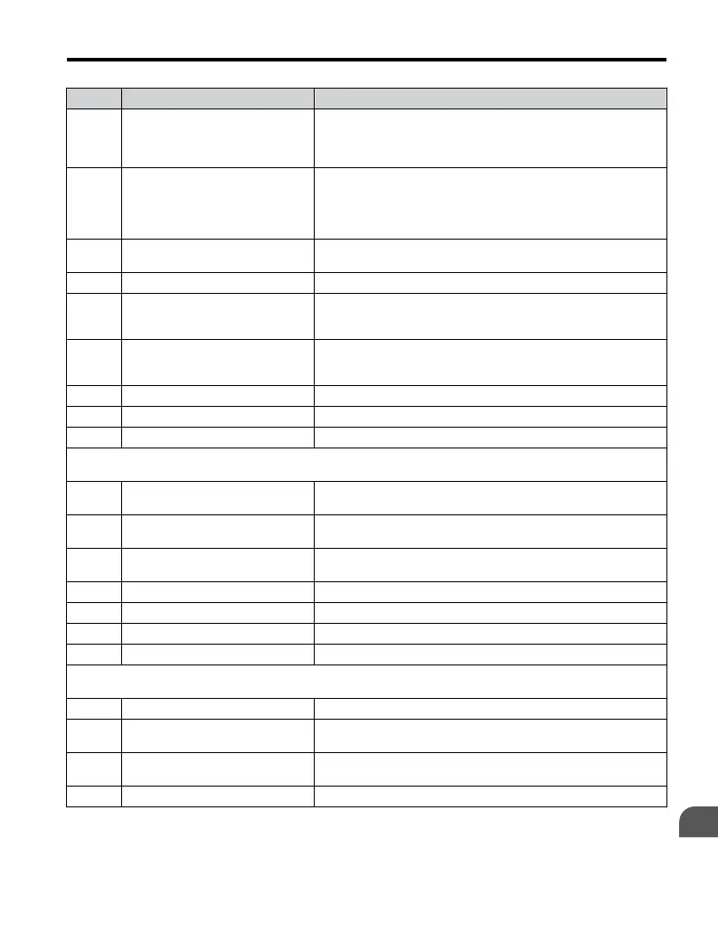
No. Name Description
b1-02 Run Command Selection 1
0: Operator - RUN and STOP keys on the digital operator.
1: Digital input terminals S1 to S7
2: Memobus communications
3: Option PCB.
b1-03 Stopping Method Selection
0: Ramp to Stop
1: Coast to Stop
2: DC Injection Braking to Stop
3: Coast with Timer (A new run command is ignored if received
before the timer expires)
b1-04 Reverse Operation Selection
0: Reverse enabled.
1: Reverse disabled.
b1-07 Local/Remote Run Selection Refer to V1000 Technical Manual for details.
b1-08
Run Command Selection while in
Programming Mode
0: Run command accepted only in the operation menu.
1: Run command accepted in all menus.
2: Prohibit entering programming mode during Run
b1-14 Phase Order Selection
Sets phase order for drive output terminals U/T1, V/T2 and W/T3.
0: Standard
1: Switch phase order
b1-15 Frequency Reference 2 Refer to V1000 Technical Manual for details.
b1-16 Run Command Source 2 Refer to V1000 Technical Manual for details.
b1-17 Run Command at Power Up Refer to V1000 Technical Manual for details.
b2: DC Injection Braking
Use b2 parameters to configure DC Injection Braking operation
b2-01
DC Injection Braking Start
Frequency
Refer to V1000 Technical Manual for details.
b2-02 DC Injection Braking Current
Sets the DC Injection Braking current as a percentage of the drive
rated current.
b2-03
DC Injection Braking Time/DC
Excitation Time at Start
Sets DC Injection Braking time at start. Disabled when set to 0.00
seconds.
b2-04 DC Injection Braking Time at Stop Sets DC Injection Braking time at stop.
b2-08 Magnetic Flux Compensation Value Refer to V1000 Technical Manual for details.
b2-12 Short Circuit Brake Time at Start Refer to V1000 Technical Manual for details.
b2-13 Short Circuit Brake Time at Stop Refer to V1000 Technical Manual for details.
b3: Speed Search
Use B3 parameters to configure Speed Search function operation.
b3-01 Speed Search Selection at Start Refer to V1000 Technical Manual for details.
b3-02 Speed Search Deactivation Current
Sets the current level at which the speed is assumed to be detected
and Speed Search is ended. Set in percent of the drive rated current.
b3-03 Speed Search Deceleration Time
Sets time constant used to reduce the output frequency during speed
search. Related to a change from max. output frequency to 0.
b3-05 Speed Search Delay Time Refer to V1000 Technical Manual for details.
B.1 Parameter Table
YASKAWA ELECTRIC TOEP C710606 47A YASKAWA AC Drive – V1000 Quick Start Guide
169
B
Parameter List

 Loading...


