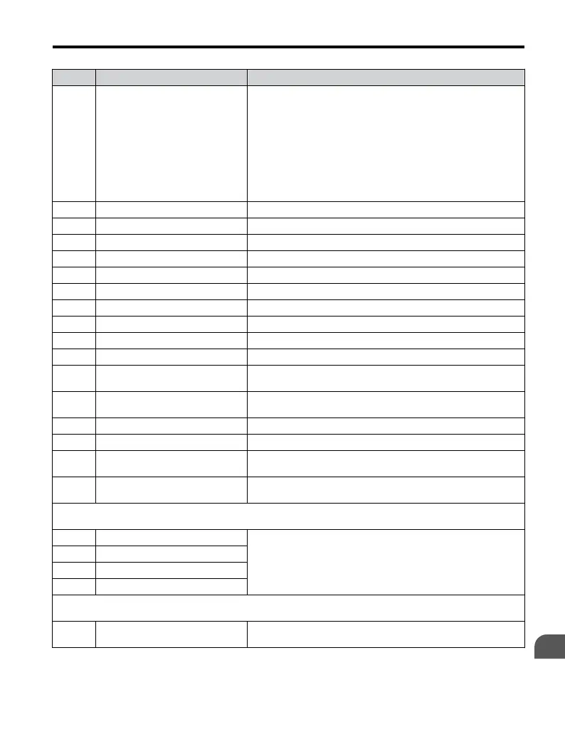
No. Name Description
b5-12
PID Feedback Reference Missing
Detection Selection
0: Disabled.
1: Feedback loss detected when PID enabled. Alarm output, operation
is continued without triggering a fault contact.
2: Feedback loss detected when PID enabled. Fault output, operation
is stopped and a fault contact is triggered.
3: Feedback loss detection when PID disabled by digital input. No
alarm/fault output. “PID feedback loss” digital output is switched.
4: PID Feedback error detection when PID disabled by digital input.
An alarm is triggered and the drive continues to run.
5: PID Feedback error detection when PID disabled by digital input.
Fault is triggered and output is shut off.
b5-13 PID Feedback Loss Detection Level Sets the PID feedback loss detection level.
b5-14 PID Feedback Loss Detection Time Sets the PID feedback loss detection delay time.
b5-15 PID Sleep Function Start Level Refer to V1000 Technical Manual for details.
b5-16 PID Sleep Delay Time Refer to V1000 Technical Manual for details.
b5-17 PID Accel/Decel Time Refer to V1000 Technical Manual for details.
b5-18 PID Setpoint Selection Refer to V1000 Technical Manual for details.
b5-19 PID Setpoint Value Refer to V1000 Technical Manual for details.
b5-20 PID Setpoint Scaling Refer to V1000 Technical Manual for details.
b5-34 PID Output Lower Limit Refer to V1000 Technical Manual for details.
b5-35 PID Input Limit Refer to V1000 Technical Manual for details.
b5-36
PID Feedback High Detection
Level
Refer to V1000 Technical Manual for details.
b5-37
PID Feedback High Level Detection
Time
Refer to V1000 Technical Manual for details.
b5-38 PID Setpoint / User Display Refer to V1000 Technical Manual for details.
b5-39 PID Setpoint Display Digits Refer to V1000 Technical Manual for details.
b5-40
Frequency Reference Monitor
Content during PID
Refer to V1000 Technical Manual for details.
Note: Available in drive software versions PRG: 1014 and later.
b5-47
Reverse Operation Selection 2 by
PID Output
Refer to V1000 Technical Manual for details.
Note: Available in drive software versions PRG: 1020 and later.
b6: Dwell Function
Use b6 parameters to configure dwell function operation.
b6-01 Dwell Reference at Start
Refer to V1000 Technical Manual for details.
b6-02 Dwell Time at Start
b6-03 Dwell Frequency at Stop
b6-04 Dwell Time at Stop
b8: Energy Saving
Use b8 parameters to configure the energy saving/conservation drive function.
b8-01 Energy Saving Control Selection
0: Disabled
1: Enabled (set b8-04)
B.1 Parameter Table
YASKAWA ELECTRIC TOEP C710606 47A YASKAWA AC Drive – V1000 Quick Start Guide
171
B
Parameter List

 Loading...


