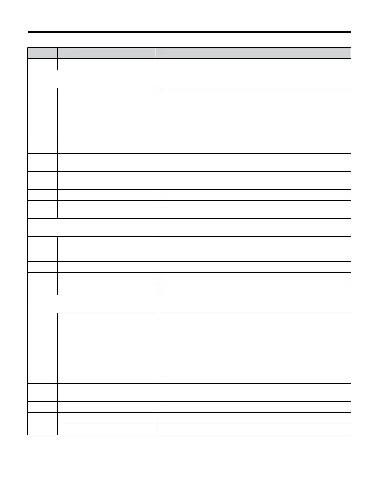
No. Name Description
L3-25 Load Inertia Ratio Refer to V1000 Technical Manual for details.
L4: Frequency Detection
Use L4 parameters to configure frequency detection operation.
L4-01 Speed Agreement Detection Level
These parameters configure the multi-function output (H2- = 2, 3,
4, 5) settings “Fref/Fout Agree 1,” “Fref/Set Agree 1,” “Frequency
Detection 1,” and “Frequency detection 2.”
L4-02
Speed Agreement Detection
Width
L4-03
Speed Agreement Detection Level
(+/-)
Refer to V1000 Technical Manual for details.
L4-04
Speed Agreement Detection Width
(+/-)
L4-05
Frequency Reference Loss
Detection Selection
0: Stop - Drive will stop
1: Run at L4-06
L4-06
Frequency Reference at Reference
Loss
Refer to V1000 Technical Manual for details.
L4-07 Frequency Detection Conditions Refer to V1000 Technical Manual for details.
L4-08
Speed Agreement Detection
Conditions
Refer to V1000 Technical Manual for details.
Note: Available in drive software versions PRG: 1016 and later.
L5: Fault Reset
Use L5 parameters to configure Automatic Restart after fault.
L5-01 Number of Auto Restart Attempts
Sets the counter for the number of times the drive attempts to restart
when the following faults occur: gF, LF, oC, oV, PF, PUF, rH, rr, oL1,
oL2, oL3, oL4, Uv1.
L5-02 Auto Restart Operation Selection Refer to V1000 Technical Manual for details.
L5-04 Fault Reset Interval Time Refer to V1000 Technical Manual for details.
L5-05 Fault Reset Operation Selection Refer to V1000 Technical Manual for details.
L6: Overtorque Detection
Use L6 parameters to configure overtorque detection.
L6-01 Torque Detection Selection 1
0: Disabled
1: oL3 at Speed Agree - Alarm
2: oL3 at RUN - Alarm
3: oL3 at Speed Agree - Fault
5: UL3 at Speed Agree - Alarm
6: UL3 at RUN - Alarm
7: UL3 at Speed Agree - Fault
8: UL3 at RUN - Fault
L6-02 Torque Detection Level 1 Sets the overtorque/undertorque detection level.
L6-03 Torque Detection Time 1
Sets the length of time an overtorque/undertorque condition must exist
before Torque Detection 1 is triggered.
L6-04 Torque Detection Selection 2 Refer to V1000 Technical Manual for details.
L6-05 Torque Detection Level 2 Refer to V1000 Technical Manual for details.
L6-06 Torque Detection Time 2 Refer to V1000 Technical Manual for details.
B.1 Parameter Table
192
YASKAWA ELECTRIC TOEP C710606 47A YASKAWA AC Drive – V1000 Quick Start Guide

 Loading...


