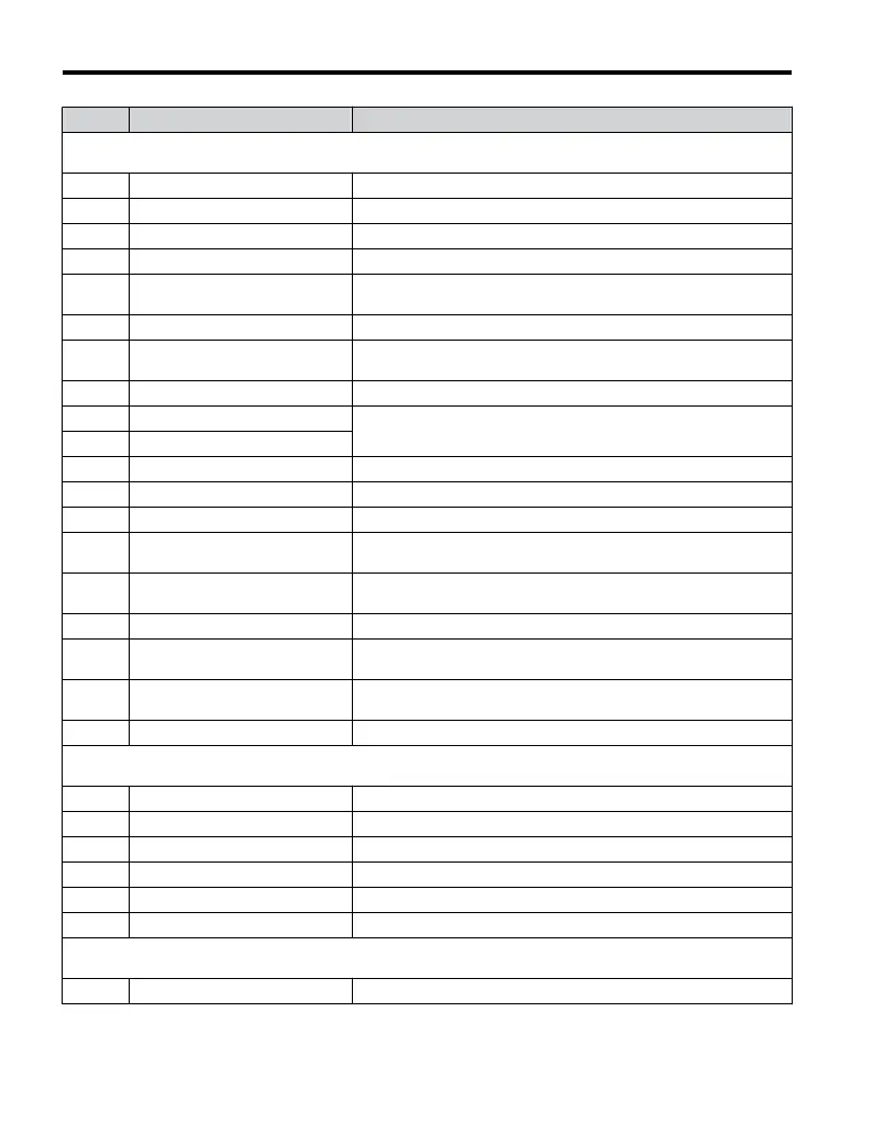
No. Name Description
U4: Maintenance Monitors
Use U4 parameters to display drive maintenance information.
U4-01 Accumulated Operation Time Refer to V1000 Technical Manual for details.
U4-02 Number of Run Commands Refer to V1000 Technical Manual for details.
U4-03 Cooling Fan Operation Time Refer to V1000 Technical Manual for details.
U4-05 Capacitor Maintenance Refer to V1000 Technical Manual for details.
U4-06
Soft Charge Bypass Relay
Maintenance
Refer to V1000 Technical Manual for details.
U4-07 IGBT Maintenance Refer to V1000 Technical Manual for details.
U4-08 Heatsink Temperature
Refer to V1000 Technical Manual for details.
Note: Available in drive software versions PRG: 1011 and later.
U4-09 LED Check Refer to V1000 Technical Manual for details.
U4-10 kWH, Lower 4 Digits
Monitors the drive output power.
U4-11 kWH, Upper 5 Digits
U4-13 Peak Hold Current Displays the peak hold current during run.
U4-14 Peak Hold Output Frequency Refer to V1000 Technical Manual for details.
U4-16 Motor Overload Estimate (OL1) 100% = OL1 detection level
U4-18
Frequency Reference Source
Selection
Refer to V1000 Technical Manual for details.
U4-19
Frequency Reference from
MEMOBUS/Modbus Comm.
Refer to V1000 Technical Manual for details.
U4-20 Option Frequency Reference Refer to V1000 Technical Manual for details.
U4-21
Run Command Source Selection Refer to V1000 Technical Manual for details.
U4-22
MEMOBUS/Modbus
Communications Reference
Refer to V1000 Technical Manual for details.
U4-23 Option Card Reference Refer to V1000 Technical Manual for details.
U5: PID Monitor
Use U5 parameters to view application-specific settings.
U5-01 PID Feedback Displays the PID feedback value.
U5-02 PID Input Refer to V1000 Technical Manual for details.
U5-03 PID Output Displays PID control output.
U5-04 PID Setpoint Displays the PID setpoint.
U5-05 PID differential feedback Refer to V1000 Technical Manual for details.
U5-06 PID Adjusted Feedback Refer to V1000 Technical Manual for details.
U6: Control Monitor
Use U6 parameters to display drive control information.
U6-01 Motor Secondary Current (Iq) Refer to V1000 Technical Manual for details.
B.1 Parameter Table
200
YASKAWA ELECTRIC TOEP C710606 47A YASKAWA AC Drive – V1000 Quick Start Guide

 Loading...


