EasyManuals Logo

YASKAWA V1000 User Manual

YASKAWA V1000
231 pages
To Next Page IconTo Next Page
To Previous Page IconTo Previous Page
Page #36 background imageLoading...
Page #36 background image
n
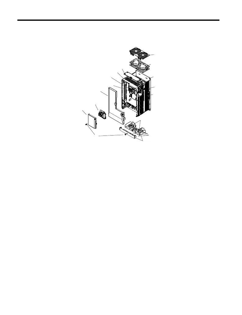
Three-Phase AC200 V CIMR-Vo2A0030F ~ 0069F
Three-Phase AC400 V CIMR-Vo4A00018F ~ 0038F
C
B
A
D
E
H
I
P
K
M
N
L
F
G
J
O
A Fan cover
B Cooling fan
C Mounting Hole
D Case and Heatsink
E Optional 24 V DC power
supply connection cover
F Cover screws
G Rubber bushing
H Bottom cover
I Front cover screws
J Terminal cover
K Terminal board Refer to
Control Circuit Terminal
Block Functions on page
66
L Front cover
M Comm port
N LED operator Refer to
Using the Digital LED
Operator on page 82
O Case
P Top cover
Figure 1.7 Exploded View of IP20/NEMA Type 1 Components
Three-Phase AC400 V CIMR-Vo4A0018F
1.2 Component Names
36
YASKAWA ELECTRIC TOEP C710606 47A YASKAWA AC Drive – V1000 Quick Start Guide

Table of Contents

Other manuals for YASKAWA V1000

Questions and Answers:

Question and Answer IconNeed help?

Do you have a question about the YASKAWA V1000 and is the answer not in the manual?

YASKAWA V1000 Specifications

General IconGeneral
Input Voltage3-Phase 200-240VAC, 3-Phase 380-480VAC
Output Voltage3-Phase 200-240VAC, 3-Phase 380-480VAC
Output Frequency0-400 Hz
Control MethodV/f control
Overload Capacity150% for 60 seconds
Protection FunctionsOvercurrent, Overvoltage, Undervoltage, Overheating, Short Circuit, Ground Fault
Communication OptionsModbus RTU
Ambient Temperature-10 to +50°C (14 to 122°F)
Storage Temperature-20°C to +65°C (-4°F to 149°F)
Humidity95% (non-condensing)
Cooling MethodForced Air Cooling
EnclosureIP20

Related product manuals