n
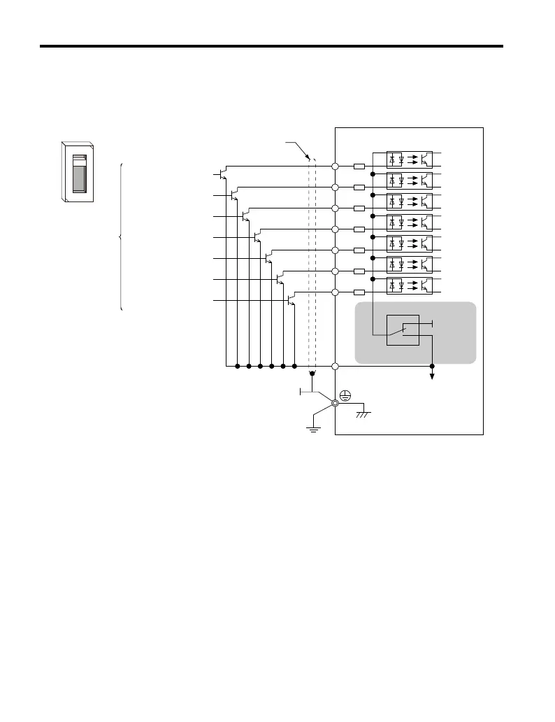
Transistor Input Signal Using 0 V Common/Sink Mode
When controlling the digital inputs by NPN transistors (0 V common/sinking mode), set the
DIP switch S3 to SINK and use the internal 24 V power supply.
Drive
Shielded cable
Forward run/stop
Reverse run/stop
External fault N.O.
Fault reset
Multi-speed step 1
Multi-speed step 2
Jog reference
Multi-function input
S1
S2
S3
S3
+24V
S4
S5
S6
S7
SC
SINK
SOURCE
SINK
SOURCE
Figure 3.20 Sinking Mode: Sequence from NPN Transistor (0 V Common)
3.6 I/O Connections
74
YASKAWA ELECTRIC TOEP C710606 47A YASKAWA AC Drive – V1000 Quick Start Guide