Cutter with material transport and CE
58
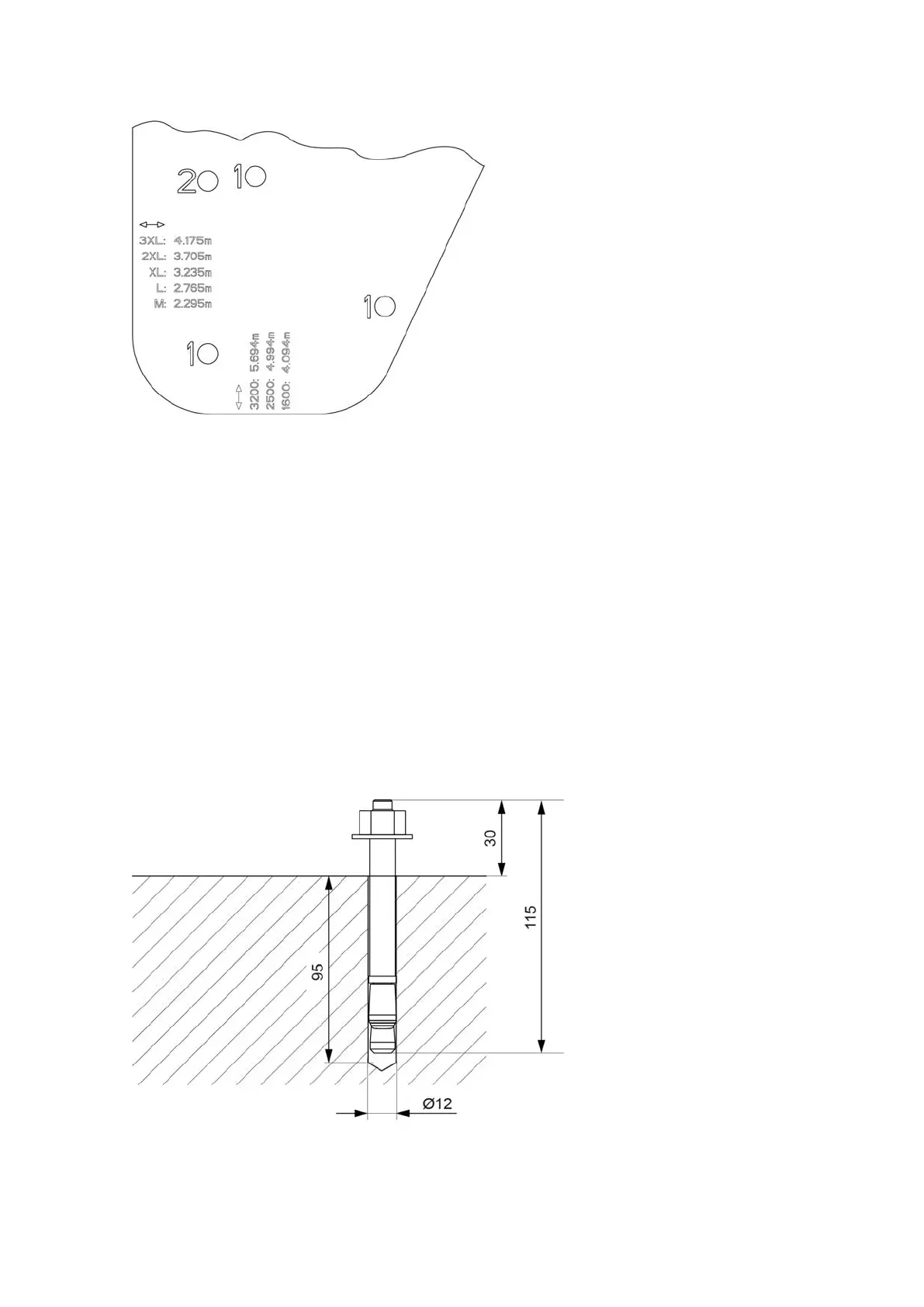
↔ Reference dimension: width from outer edge to outer edge
↕ Reference dimension: length from outer edge to outer edge
A Place the two drilling templates according to the labeling on the bases on one side of the cutter.
For example, front left and rear left.
B Align the drilling templates to the base frame.
a) Use an angle, string or a long, straight board, for example, as an aid.
b) Place the aid along the support line for alignment and on the bases.
C Use the imprint on the drilling template or the "reference dimension" assembly base to check the
indicated dimension (see Diagrams on page 99).
D Mark the drill holes. Make sure to use the holes with the appropriate marking (1 = front, 2 = rear).
E Mark the drill holes on the opposite side in the same way.
8.3.2 Drilling holes and placing segment anchors



 To Next Page