PBX Networking
161
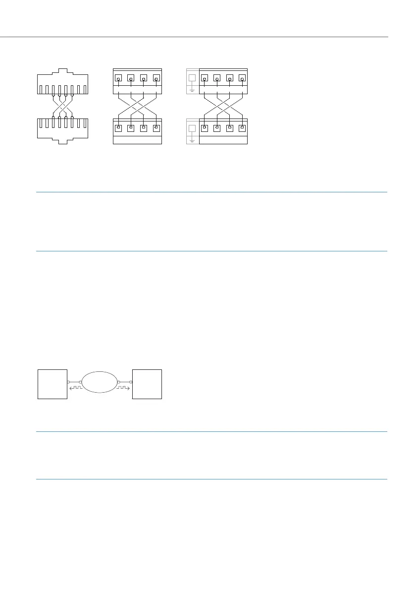
Wiring of a direct connection
Note
If you use an S
0
port on an interface card (pressure terminal) and an S
0
port with an
RJ45 jack for the direct connection, make sure you make the necessary changes to
the port assignment (see S0 Ports on Interface Cards starting on page 53).
The external S
0
-ports of a gateway can also be used for a direct connection.
Connection via an Active Transmission System
For distances exceeding the range of a direct connection, an active transmission
system can increase the range to up to 50 km. Normally the L1 master is the trans-
mission system for the two connected PBXs. For the protocol layers L2 and L3, one
PBX is normally the protocol master and the other PBX is the protocol slave.
Connection by an active transmission system
Note
The active transmission system itself gets its L1 clock either from the network opera-
tor or from a clock generator connected by wire.
12345678
87654321
PBX 1, S
0
ext
PBX 2, S
0
ext
(RJ-45 socket)
OpenCom 130: PBX 1, S
2M
PBX 2, S
2M
(Pressure clamps)
Rx+ Rx- Tx+ Tx-
Rx+ Rx- Tx+ Tx-
OpenCom 150: PBX 1, S
2M
PBX 2, S
2M
(Pressure clamps)
Rx+ Rx- Tx+ Tx-
Rx+ Rx- Tx+ Tx-
PBX 1
L1 slave
L2 master
L3 master
PBX 2
L1 slave
L2 slave
L3 slave
Transmission
System
L1 master
 Loading...