S
2M
Connector Module
73
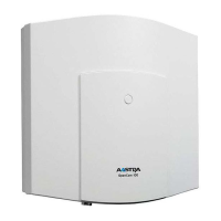
4. Insert the S
2M
module into the slots, making sure you insert the LED side of the
module into the upper slot (B).
Position of the LEDs on the
S
2M
module
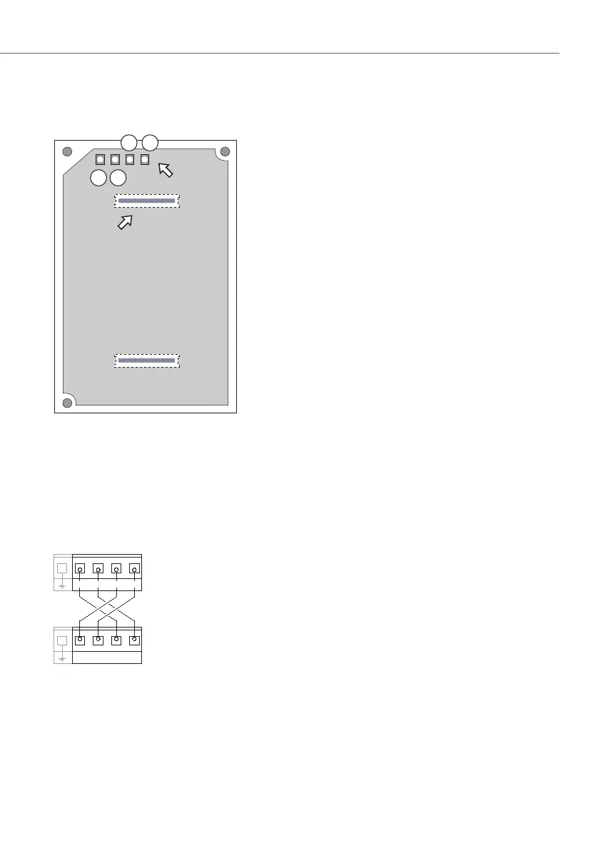
5. Wire the S
2M
port of the connector module to the NT or the other PBX according to
the following drawing. Make sure the RX and TX lines are crossed over (connect
the RX lines of the OpenCom 130 / 150 to the TX lines of the other PBX).
Example of the wiring of the S2M port for two OpenCom 130 / 150s
4
3
1 2
S
2M
LEDs
S
2M
slot
(Underside of the module board)
PBX 1, S
2M
PBX 2, S
2M
(Pressure clamps)
Rx+ Rx- Tx+ Tx-
Rx+ Rx- Tx+ Tx-