Installation Configuring the CEI-620
CEI-100/CEI-200/CEI-x20 User’s Manual 15
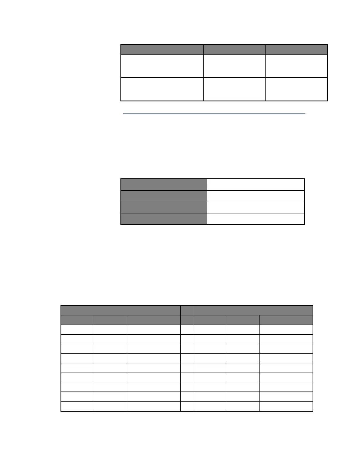
ARINC 573/717
Bipolar return-to-zero encoding
#1
TX+: pin P1-1
TX-: pin P1-26
ARINC 573/717
Harvard bi-phase encoding
#1, #2
TX+: pin P1-1
TX-: pin P1-2
For external wrap, connect each transmit signal to the corresponding
receive signal (e.g., TX1+ to RX1+, TX1- to RX1-, etc.) In addition,
connect each discrete output to the corresponding discrete input.
The mating connectors for P1 and P2 are as shown in Table 9:
Table 9. Mating Connectors for P1 and P2
CEI-620 Transition Cable Pin Out
Table 10 defines the CONCEI-620 cable provided with each CEI-620.
The cable is approximately three feet in length. There is a Champ 0.8mm
50 pin connector (AMP 787131-1) on one end. The other end is a standard
subminiature-D, 50-pin plug connector (AMP p/n 205212-3 or equivalent).
Table 10. CEI-620 Transition Cable Pin Out
Artisan Technology Group - Quality Instrumentation ... Guaranteed | (888) 88-SOURCE | www.artisantg.com