Installation Configuring the CEI-100
CEI-100/CEI-200/CEI-x20 User’s Manual 32
Configuring the CEI-100
This section provides configuration information for the CEI-100.
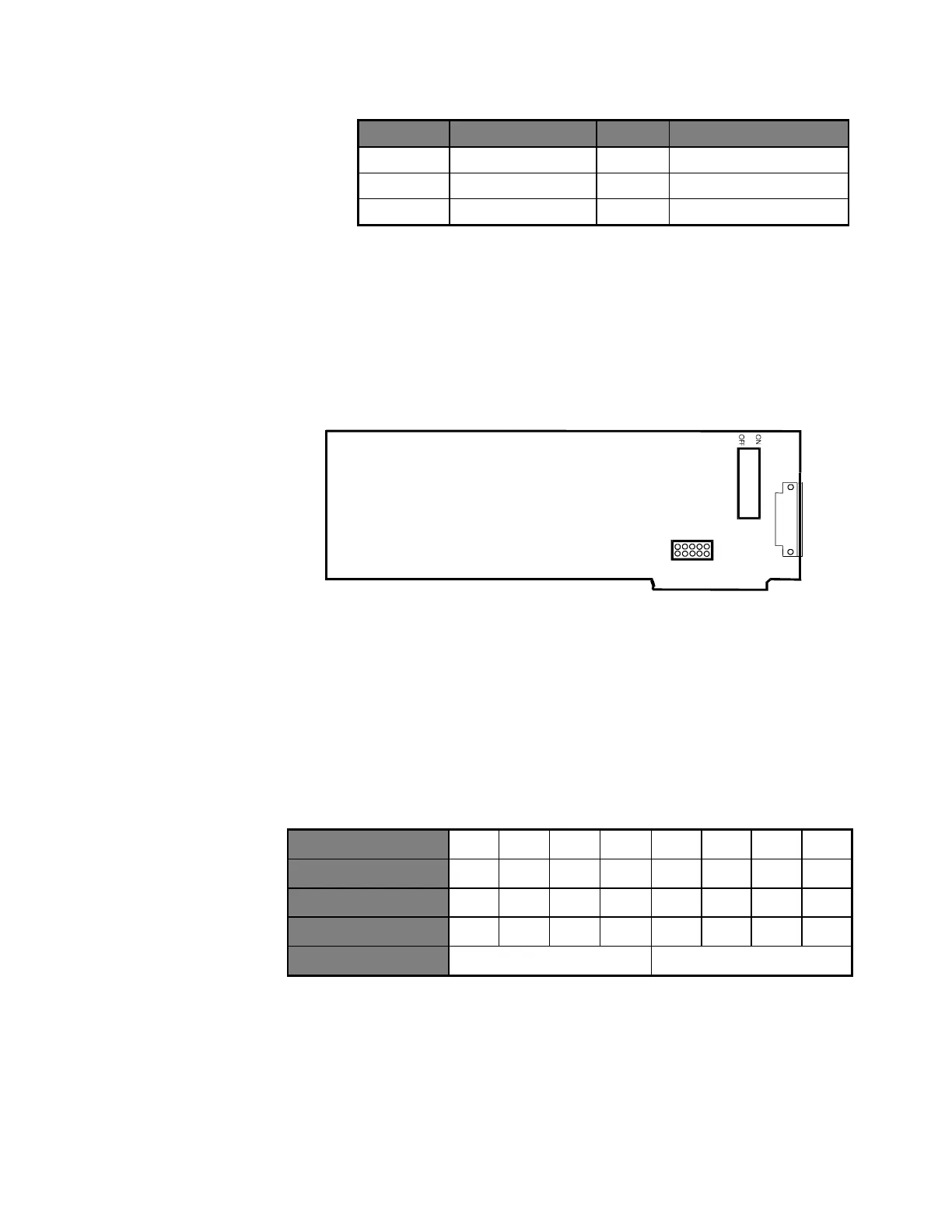
CEI-100 Outline Drawing
2
4
6
8
1
0
1
3
5
7
9
JP1
10
1
S
w
i
t
c
h
U
2
6
Figure 17. CEI-100 Outline Drawing
CEI-100 Base Memory Address
Switches 1 through 6 on the dipswitch at U26 set the CEI-100 base
address. The following example demonstrates the default address of CC00.
Table 28. Default Address of CC00 Example
Other sample settings for switches 1 through 6 respectively generate the
following base segment addresses:
CE00 = Off On On Off Off Off
D000 = Off On Off On On On
D200 = Off On Off On On Off
E000 = Off Off On On On On
Artisan Technology Group - Quality Instrumentation ... Guaranteed | (888) 88-SOURCE | www.artisantg.com