For external wrap, connect each discrete output to the corresponding
discrete input.
An optional 15” adapter cable that brings all of the CEI-520/520A P3
signals out to a 37-pin D-sub female connector (mounted on a PC
expansion card end-panel) is available. For details, search our web site for
the part number CONM50-D37. A 30” version of the adapter cable is also
available (CONM50-D37-30).
A mating connector for P3 on the CEI-520/520A is shown in Table 16.
Table 16. CEI-520/520A P3 Mating Connector
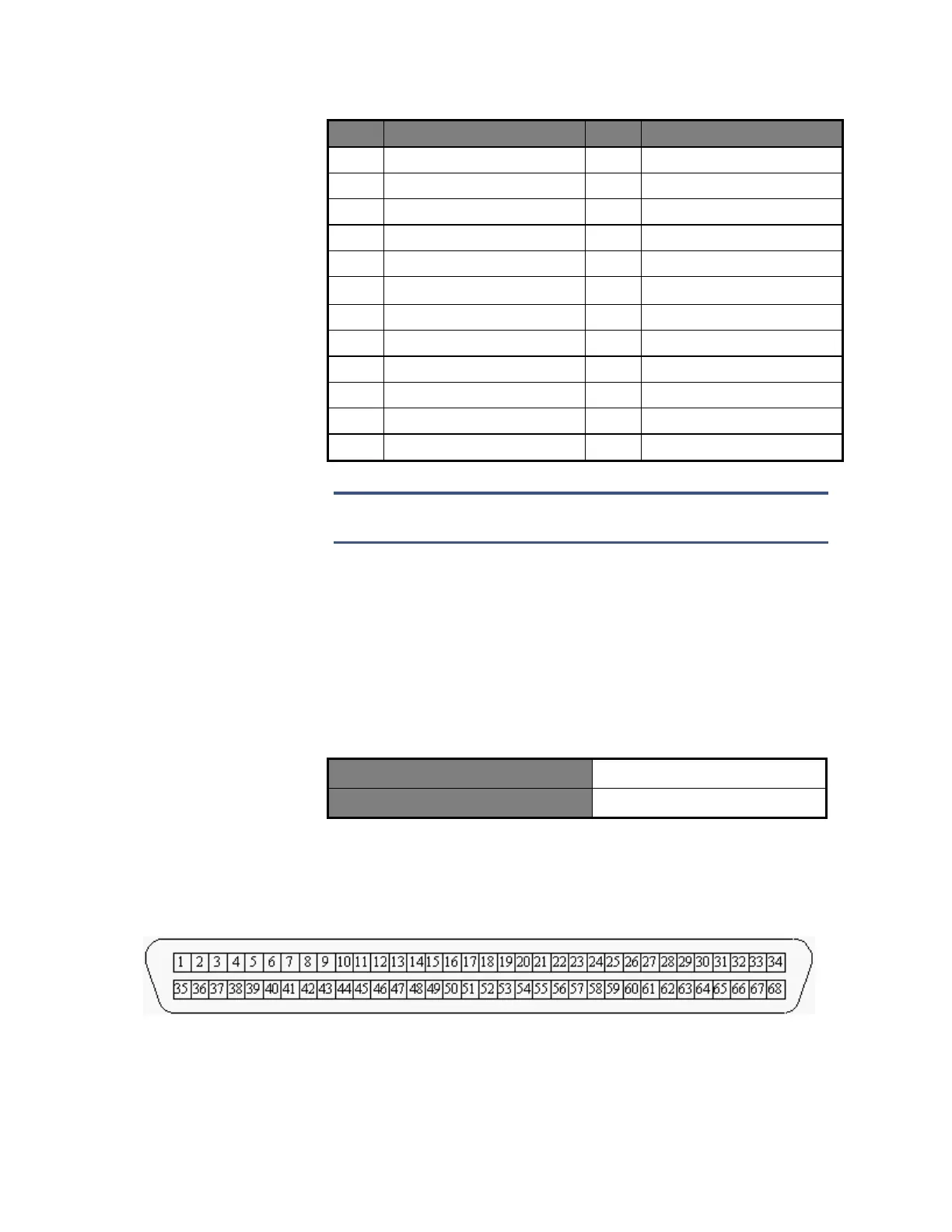
CEI-520/520A Transition Cable Pin Out
Figure 9 shows how the pins are numbered on the cable connector.
Figure 9. 68-pin connector for the CEI-520/520A Transition Cable
Consult the datasheet provided with each cable for pinout assignments.
Artisan Technology Group - Quality Instrumentation ... Guaranteed | (888) 88-SOURCE | www.artisantg.com