Installation Configuring the CEI-200
CEI-100/CEI-200/CEI-x20 User’s Manual 29
Configuring the CEI-200
This section provides configuration information for the CEI-200. Jumper
J1 is factory-set and must not be modified.
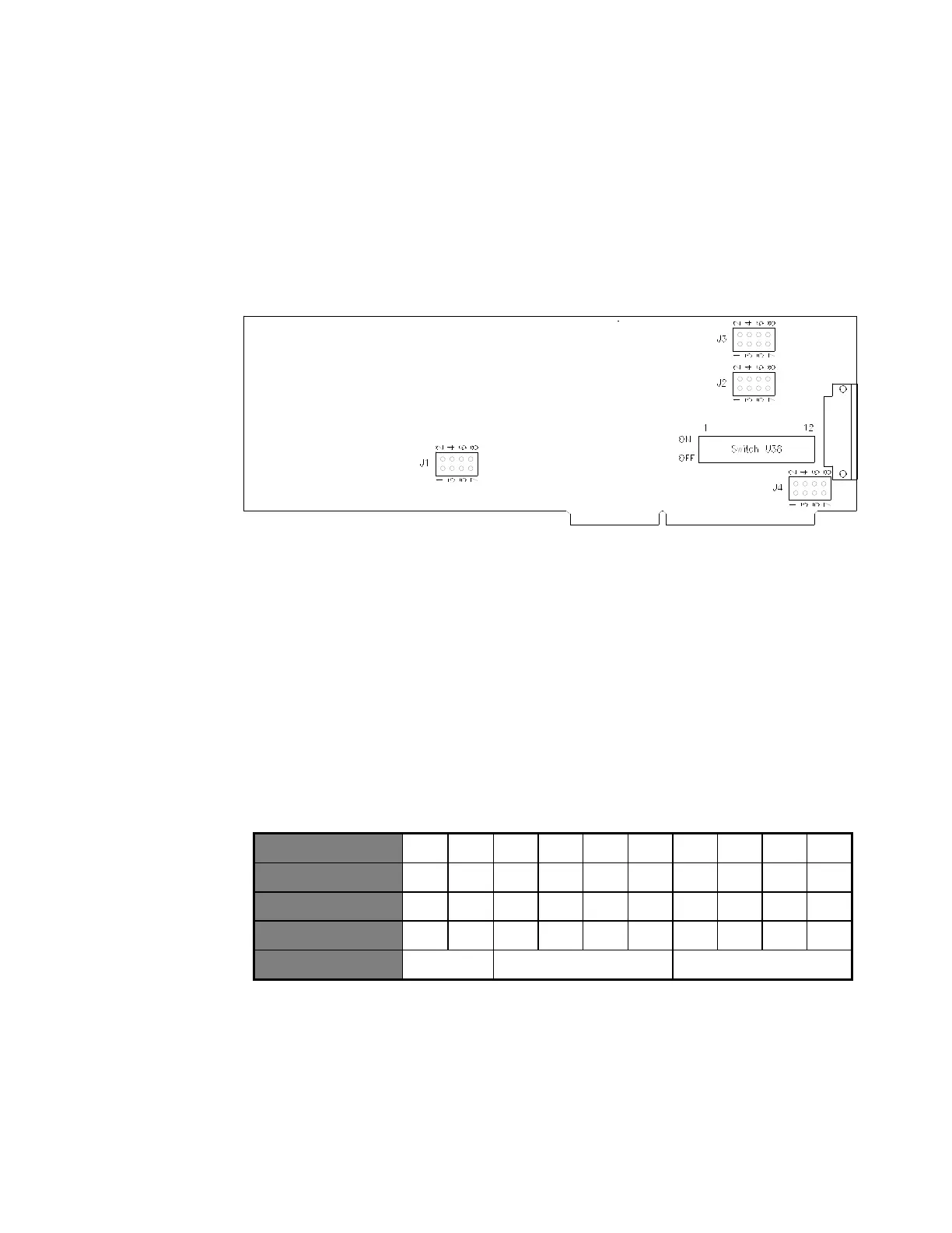
CEI-200 Outline Drawing
Figure 15. CEI-200 Outline Drawing
CEI-200 Base Memory Address
Switches 1 through 7 set the base memory address for the CEI-200.
Switches 1 and 2 must be left in the ON position. They are for future
software support. The following table demonstrates mapping of switch
positions to address bits. It uses the default address of D000 (hex) as an
example. The CEI-200 takes up 32Kb of memory space.
Table 23. CEI-200 Mapping of Switch Positions to Address Bits
Other sample settings for switches 1 through 7 respectively generate the
following base memory addresses:
D800 = On On Off Off On Off Off
E000 = On On Off Off Off On On
Artisan Technology Group - Quality Instrumentation ... Guaranteed | (888) 88-SOURCE | www.artisantg.com