Installation Configuring the CEI-200
CEI-100/CEI-200/CEI-x20 User’s Manual 30
CEI-200 Base I/O Address
Switches 8 through 12 set the base I/O address for the CEI-200. The
following example demonstrates the default address of 380 (hex).
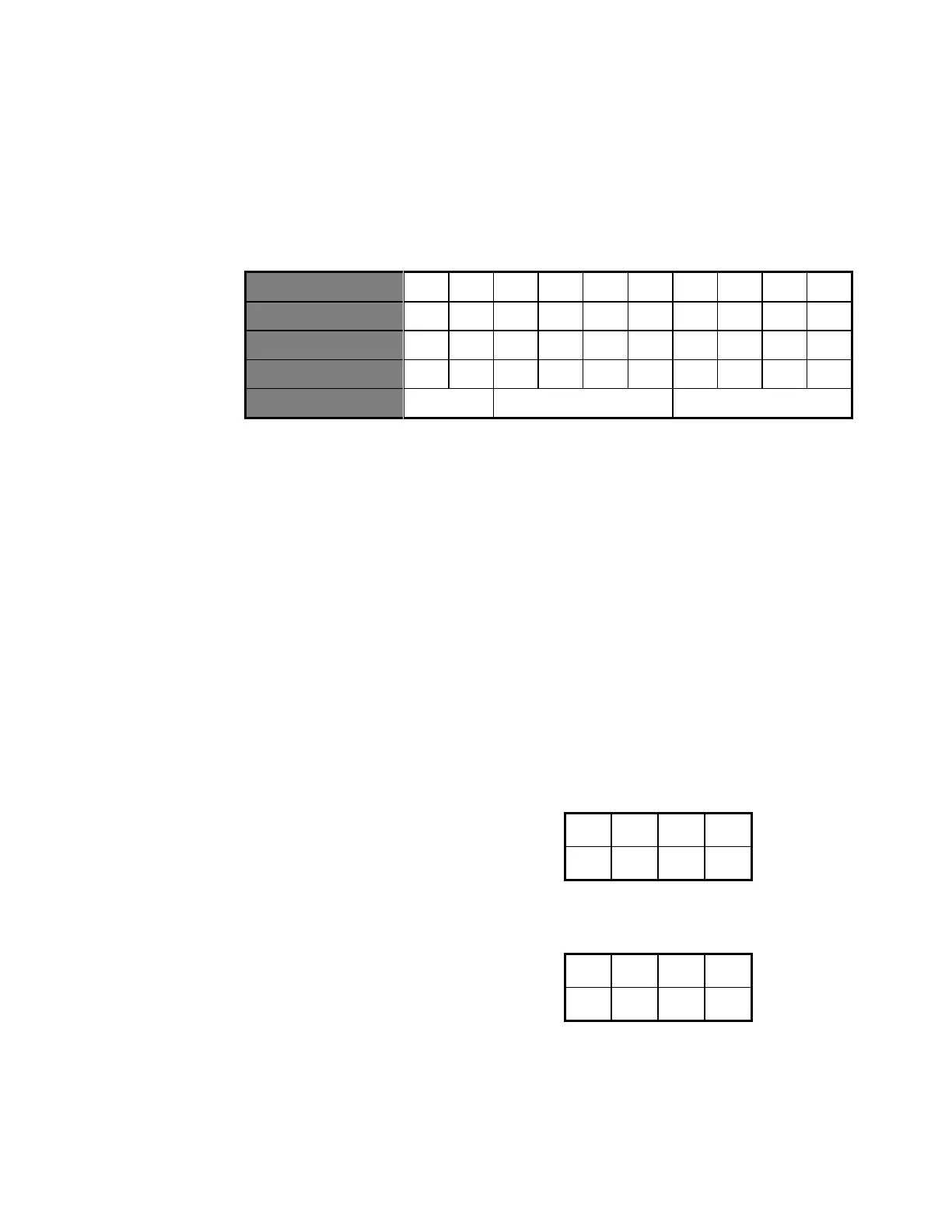
Table 24. Default Address of 380 (hex) Example
Other sample settings for switches 8 through 12 respectively generate the
following base I/O addresses:
388 = Off On On On Off
390 = Off On On Off On
CEI-200 Interrupts and Slew Rate
Jumper blocks J2 and J3, located in the upper right corner of the board, are
used to set the ARINC transmit data slew rates. With no jumpers in place,
slew rates are set for the high (100Kbs) bit rate. To set up a channel for
low speed transmission, attach two jumpers for each channel. For
example, to set up channel 2 for low speed transmission, attach one jumper
on J2 between locations 5-6 and one jumper between locations 7-8.
Table 25. Jumper blocks J2 and J3
Artisan Technology Group - Quality Instrumentation ... Guaranteed | (888) 88-SOURCE | www.artisantg.com