Installation Configuring the CEI-200
CEI-100/CEI-200/CEI-x20 User’s Manual 31
Jumper block J4 is used for interrupt control. To enable an interrupt,
select one of the four-interrupt levels (IRQ3, IRQ4, IRQ5, or IRQ7) and
install its corresponding jumper. For example, a jumper between locations
1 and 2 enables interrupts on IRQ3. Interrupts are not required for normal
operation of the board.
Table 26. Jumper block J4
PC bus connector
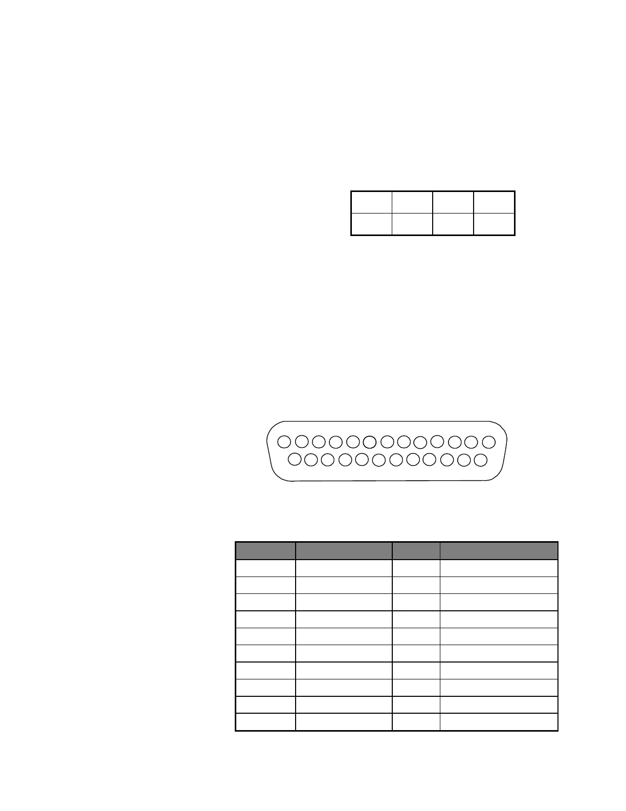
CEI-200 ARINC Connector Pin Out
To couple the CEI-200 to ARINC devices, a 25-pin Subminiature “D” type
connector on the end panel is provided. The connector pin numbers are
listed in Figure 16 and Table 27.
To build a loop back connector for the external wrap-around test, connect
the following three pin groups: (1,2,3), (4,5,6), (7,8,9), (10,11,12),
(14,15,16), (17,18,19), (20,21,22), and (23,24,25). This connects
receivers 1 and 2 to transmitter 1, receivers 3 and 4 to transmitter 2, etc.
Artisan Technology Group - Quality Instrumentation ... Guaranteed | (888) 88-SOURCE | www.artisantg.com