Installation Configuring the CEI-520 and CEI-520A
CEI-100/CEI-200/CEI-x20 User’s Manual 20
effectively implement a CEI-520/520A-xx channel mapping. The
documentation for the AR_LOADSLV routine describes how to enable
this mode of operation.
The CEI-520/520A has a rear panel 68-pin receptacle connector (SCSI-3
compatible with rails and latch blocks). A mating connector (using a
SCSI-3 cable plug connector with wire lacing termination) is shown in
Table 14.
Table 14. CEI-520/520A P2 Mating Connector
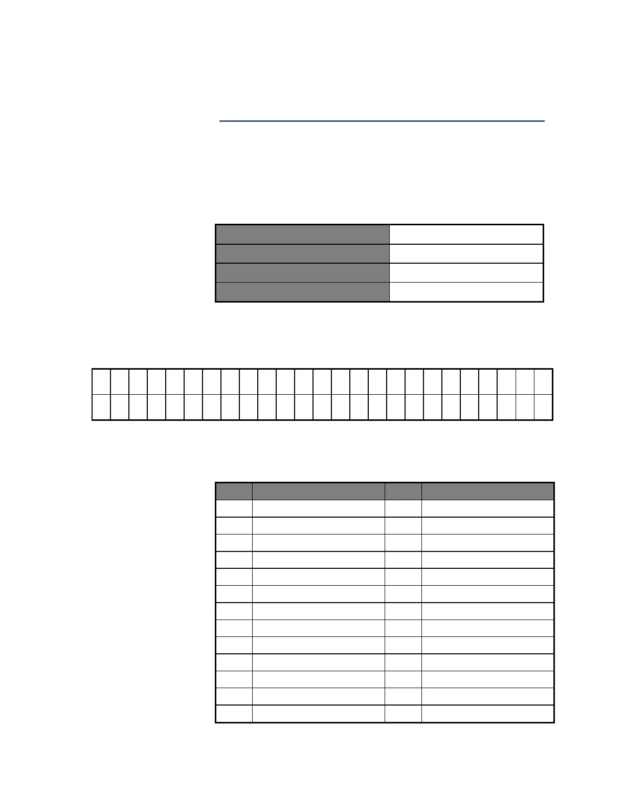
The CEI-520/520A uses a 50-pin IDC-style connector (shown in Figure 8)
for discrete input/output. Table 15 shows the pinout information for the
discrete I/O connector.
Figure 8. 50-pin IDC-style Discrete I/O connector (3M Part Number 2550-6002-UB)
Table 15. Top View – Discrete Input/Output Connector (P3)
Artisan Technology Group - Quality Instrumentation ... Guaranteed | (888) 88-SOURCE | www.artisantg.com