Configuring the CEI-520 and CEI-520A
This section provides configuration information for the CEI-520 and the
CEI-520A.
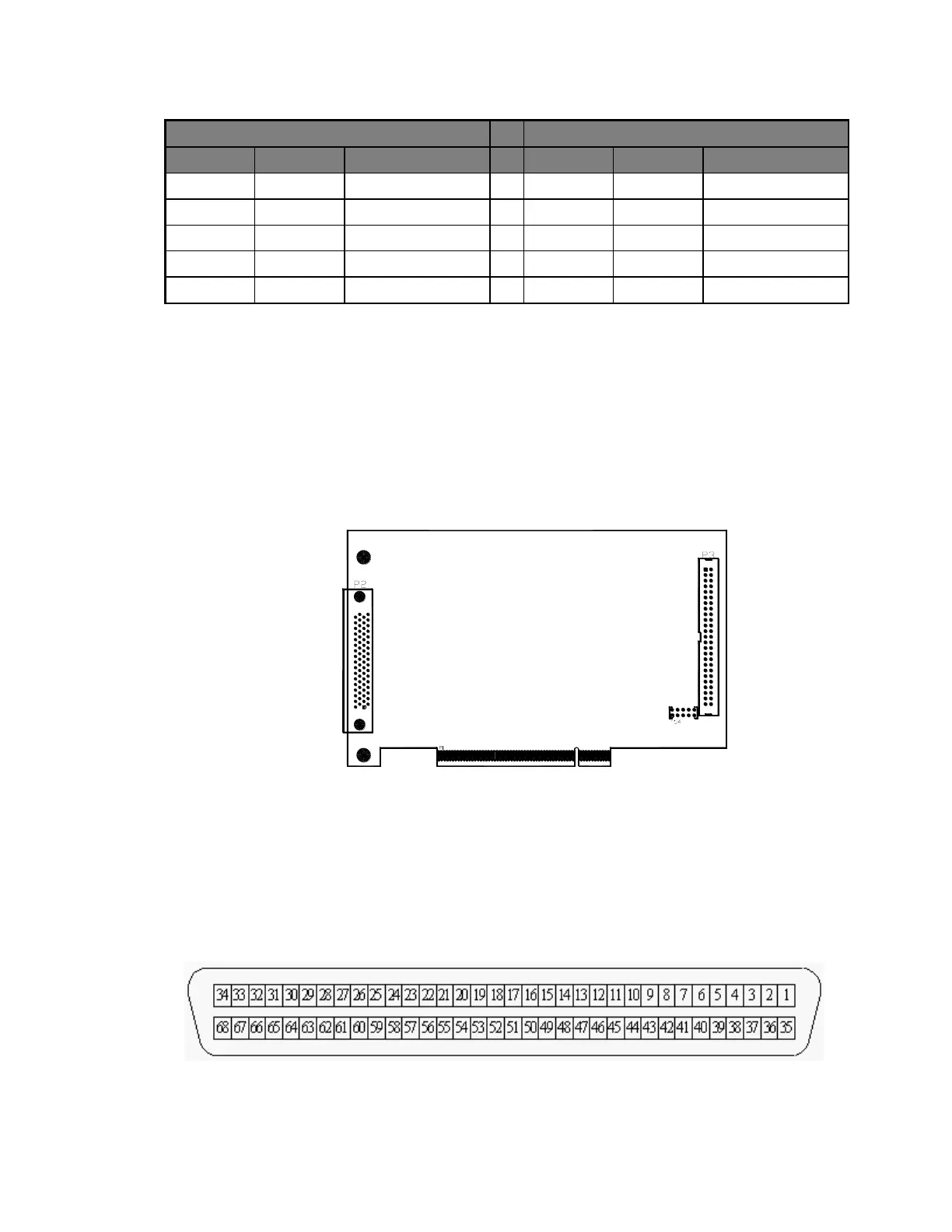
CEI-520/520A Outline Drawing
Figure 6. CEI-520/520A Outline Drawing
CEI-520/520A Input/Output Connector Pin Out
To couple the CEI-520/520A to ARINC devices using the rear panel, the
following rear panel connector is provided (AMP/Tyco 787171-1).
Figure 7. 68-pin Receptacle Connector (SCSI-3 compatible with rails and latch blocks, view
facing receptacles)
Artisan Technology Group - Quality Instrumentation ... Guaranteed | (888) 88-SOURCE | www.artisantg.com