Hardware description
15
Hardware description
What this chapter contains
This chapter describes a typical drive system and the hardware of the inverter
modules. The information is valid for all ACS800-104 inverter modules.
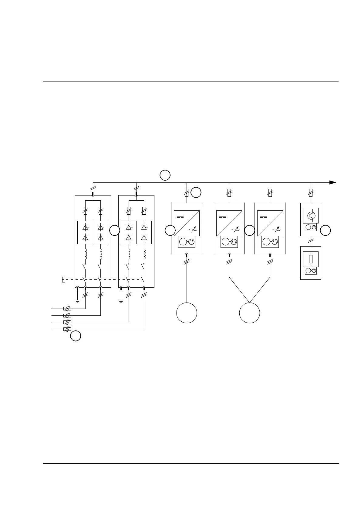
Typical drive system
The diagram below depicts a common DC bus drive system.
1 – Input (AC) fuses
2 – Supply unit (in this example, consisting of two supply modules)
3 – DC bus
4 – Inverter DC fuses
5 – Inverter units (in this example, one of the units consists of two
inverter modules connected in parallel)
6 – Brake chopper(s) (optional)
M
3~
M
M
MMM
M
3~
2
1
5 5 6
3
4
 Loading...


