58
Power connections – Frame R8i and multiples
See also the document ACS800 MultiDrive; Planning the Electrical
Installation (3AFE 64783742 [English]).
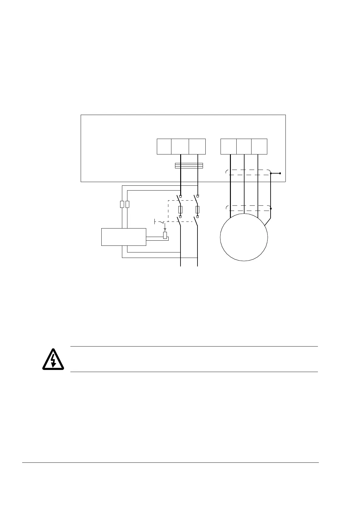
Wiring diagram
DC connection
The DC connection busbars are located at the top of the module. See the
dimensional diagrams for the exact location. Busbar sets for the DC connection with
holders for common mode filter toroids are available, and pictured in the chapter
Cabinet construction.
WARNING! Make sure the M12 screws used for connecting the DC link to the
inverter module do not extend into the module farther than 20 mm.
INPUT
OUTPUT
UDC+
Inverter module
UDC-
L+ L-
V2 W2U2
ASFC-01C
Switch fuse controller
U1
V1
W1
3~
Motor
PE
PE
Common mode filtering (optional)
 Loading...


