56
DC and motor connections
Charging circuit
Installing a switch fuse between the inverter module(s) and the DC link necessitates
a charging circuit. In frame R6i units, the charging circuit consists of charging
resistors and a contactor; with R7i, the charging is monitored by a charging controller
unit (type NCHM-x1C). The main components of the charging circuit (apart from the
fuses and fuse bases) are included in the switch fuse kits.
For frame R6i, the minimum wire sizes to be used in the charging circuit are as
follows:
• From contactor to resistors; between resistors (690 V units): 2.5 mm
2
(AWG 14)
• Charging control (wiring to/from NPOW): 0.75 mm
2
(AWG 18).
For frame R7i, the minimum wire sizes to be used in the charging circuit are as
follows:
• DC bus to fuses: 2.5 mm
2
(AWG 14), double-insulated
• NCHM to ground: 2.5 mm
2
(AWG 14)
• From fuses/NCHM to charging resistors: 1.5 mm
2
(AWG 14)
• Switch fuse auxiliary contact/solenoid wiring; auxiliary voltage supply to NCHM:
0.75 mm
2
(AWG 18).
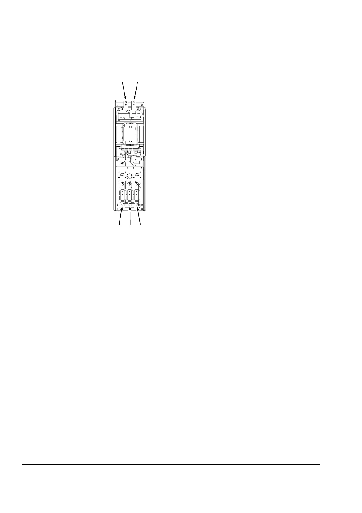
L+ (UDC+) L– (UDC–)
V2U2 W2
DC input
Motor output
 Loading...


