59
Charging circuit
Installing a switch fuse between the inverter module(s) and the DC link necessitates
a charging circuit. The charging circuit contains two resistors per inverter module
and a switch fuse controller (type ASFC-01C). The resistors and the controller are
included in the switch fuse kits.
The minimum wire sizes to be used in the charging circuit are as follows:
• DC bus to fuses: 2.5 mm
2
(AWG 14), double-insulated
• ASFC to ground: 2.5 mm
2
(AWG 14)
• From fuses/ASFC to charging resistors: 1.5 mm
2
(AWG 14)
• Switch fuse auxiliary contact/solenoid wiring; auxiliary voltage supply to ASFC:
0.75 mm
2
(AWG 18).
The ASFC is also to be connected to the AINT board of the inverter module(s) by a
fibre optic link. See this chapter under Control connections.
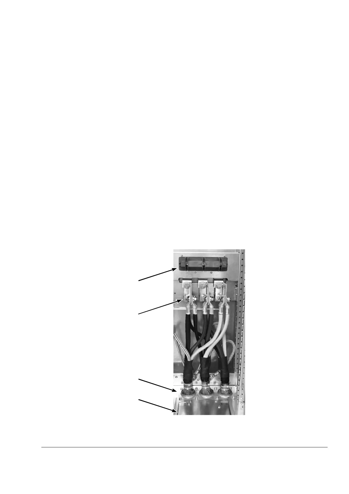
Motor connection
The motor connection of frame R8i inverter modules is located at the back of the
module so that a quick connector can be used, enabling easy extraction of the
module from the cabinet for maintenance. The chassis socket – available separately
with different mounting parts – is attached to the rear part of the cubicle (see the
examples in the chapter Cabinet construction). The picture below shows a cabling
example.
Chassis socket with
mounting plate
Gland plate
Output busbars
Lower module
guide
 Loading...


