53
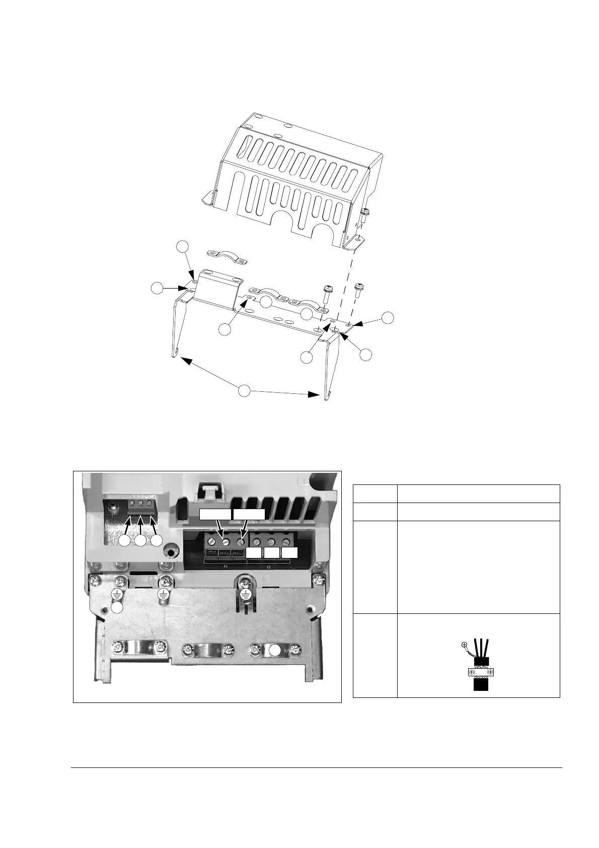
Frame R2i to R4i power connections
Frame R3i pictured.
Cover
Cable clamps
Back plate
1
4
3
3
2
2
4
8
8
Input (DC) power
cable clamp
Item No. Information
1 Connect to PE busbar of cabinet.
2…4 Prevention of unexpected start (optional).
See also the chapter Circuit diagrams.
2 L (95…265 V AC). Voltage must be ON for
the inverter to start.
3 N
4 PE
5 Strip off the outer sheathing of the cable at
the clamp.
5
1
Motor cable
clamp
234
UDC+ UDC–
W2V2U2
 Loading...


