63
Control connections
Frame R2i to R5i
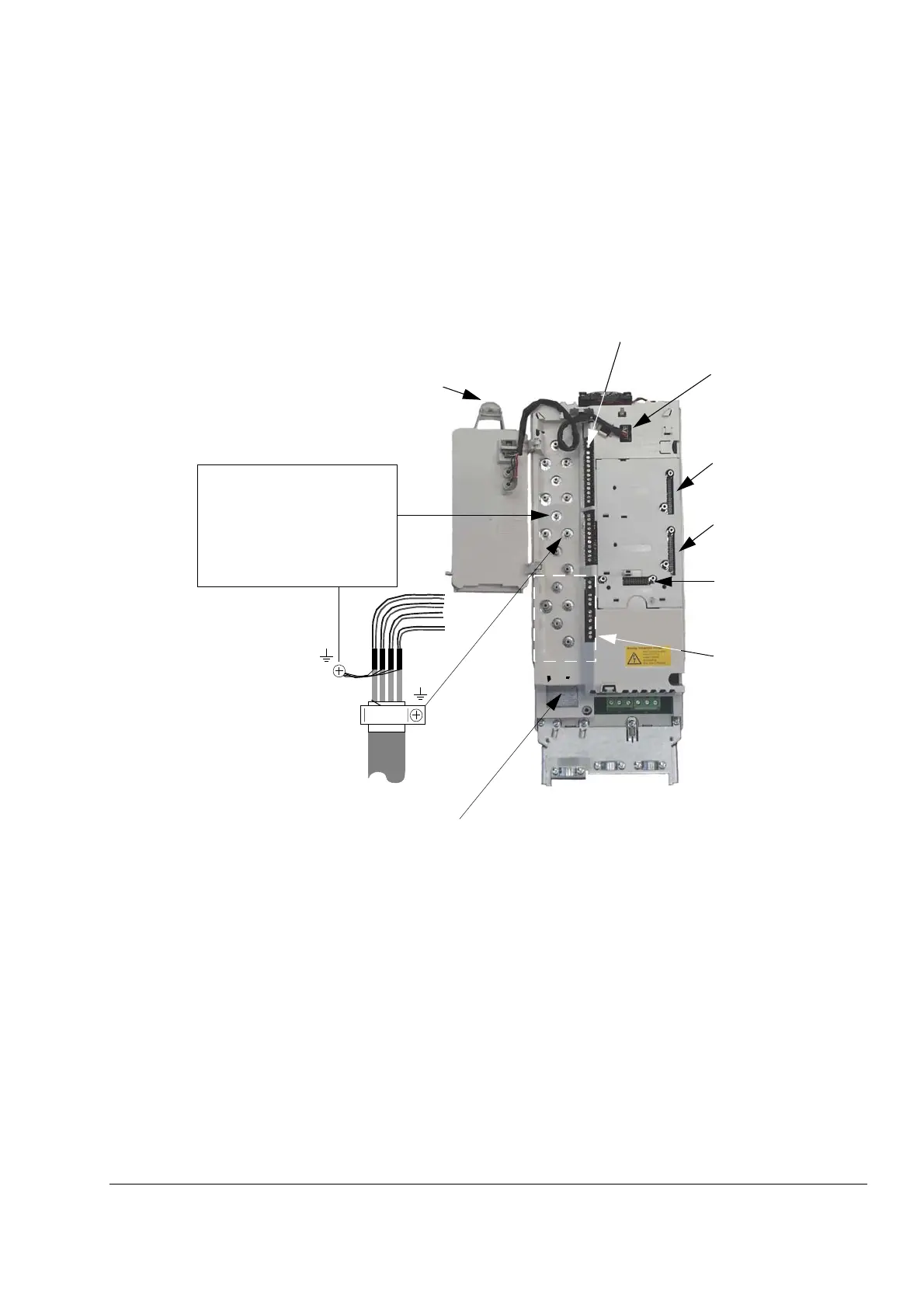
These inverter modules have a built-in RMIO (Motor control and I/O) board. For
descriptions of the terminals, see the chapter Motor control and I/O board (RMIO).
Frame R2i to R4i (R3i pictured)
1
2
3
4
I/O cables: Ground the
control cable shields in the
holes with screws. See 360
degrees grounding of I/O
cables on page 63
DDCS communication
option module 3:
RDCO
Install shroud
(included) on the relay
outputs if voltage at the
terminals exceeds
50 V AC
The control cable connection
terminals are exposed when the
control panel platform (if present) is
turned aside by pulling this lever. Be
careful – do not use excess force
when pulling.
Optional module 1
Optional module 2
RMIO X39 for control
panel cable
Detachable I/O terminals (pull upwards)
Prevention of unexpected start
(optional) – see Frame R2i to R4i
power connections on page 53
 Loading...


