Hardware description
22
Control interfaces
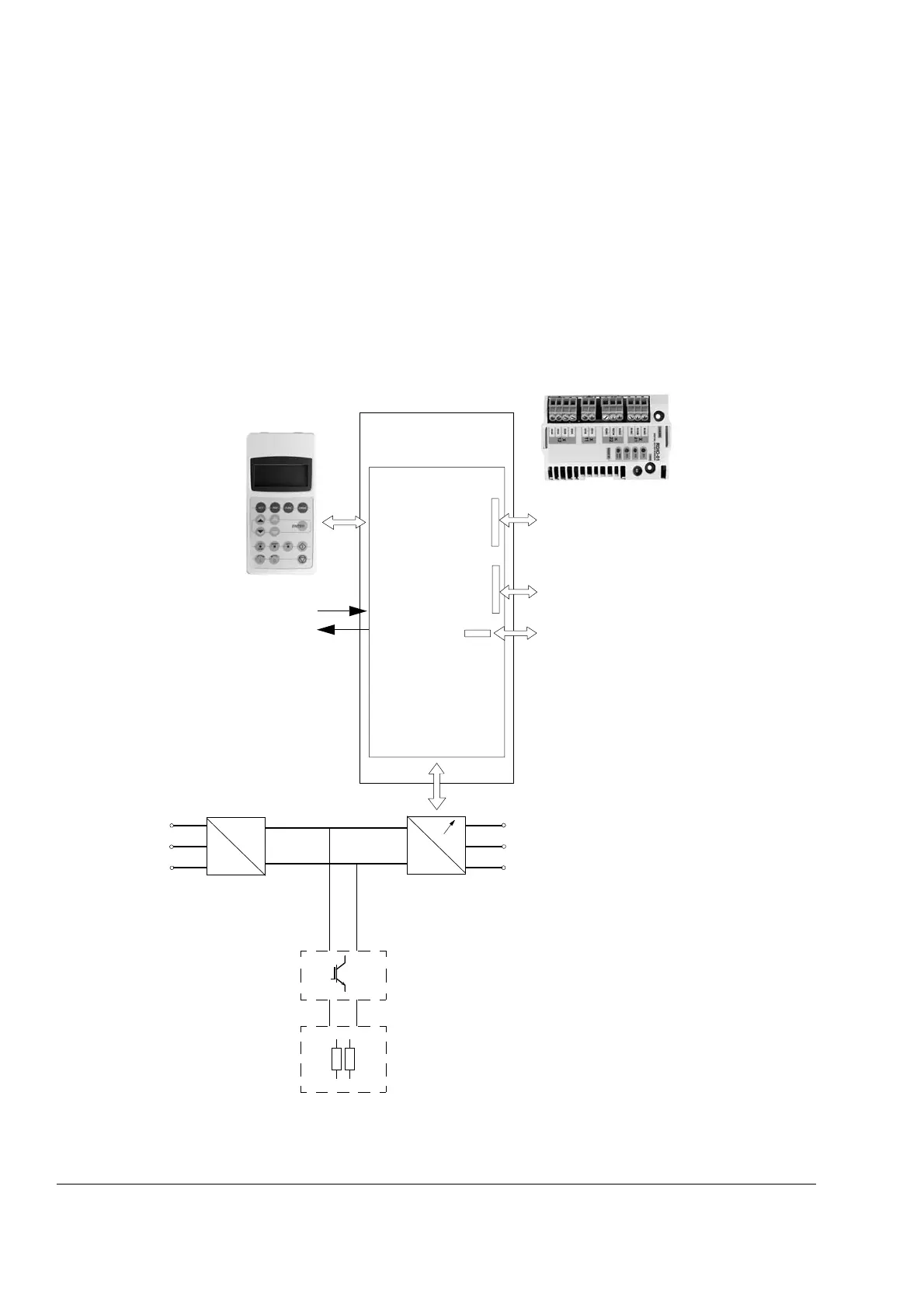
The following diagram shows the control interfaces and I/O options of the inverter
unit.
The front cover of frame R5i has a platform for the CDP 312R control panel; frames
R2i to R4i require an additional platform kit if the panel needs to be mounted on the
module.
For frame R6i to R8i (and multiples), the control panel is to be installed on a door
platform, available as a separate kit.
See the chapter Electrical installation for more information.
~
=
~
=
*Motor control
and I/O board
(RMIO)
External control via
analogue/digital inputs
and outputs
Input power
To motor
Optional module 1: I/O extension (RAIO,
RDIO), pulse encoder interface (RTAC), or
fieldbus adapter (e.g. RMBA, RDNA, RPBA)
Optional module 2: I/O extension (RAIO,
RDIO) or pulse encoder interface (RTAC)
Optional module 3: DDCS communication
option (RDCO-0x)
The fibre optic channels provided by the
RDCO module can be used for I/O extension
(using NAIO/NDIO modules), pulse encoder
connection (NTAC module), fieldbus
connection (Nxxx fieldbus adapter modules),
PC connection (DriveWare
®
PC tools), or
master/follower connection.
Brake choppers and
resistors (optional)
*Drive control unit
(RDCU)
CDP 312R Control panel
and related accessories
Supply unit
Inverter unit
*In frame sizes R2i to
R5i, the RMIO board is
built in the inverter
module instead of a
separate RDCU unit.
 Loading...


