55
Power connections – Frames R6i and R7i
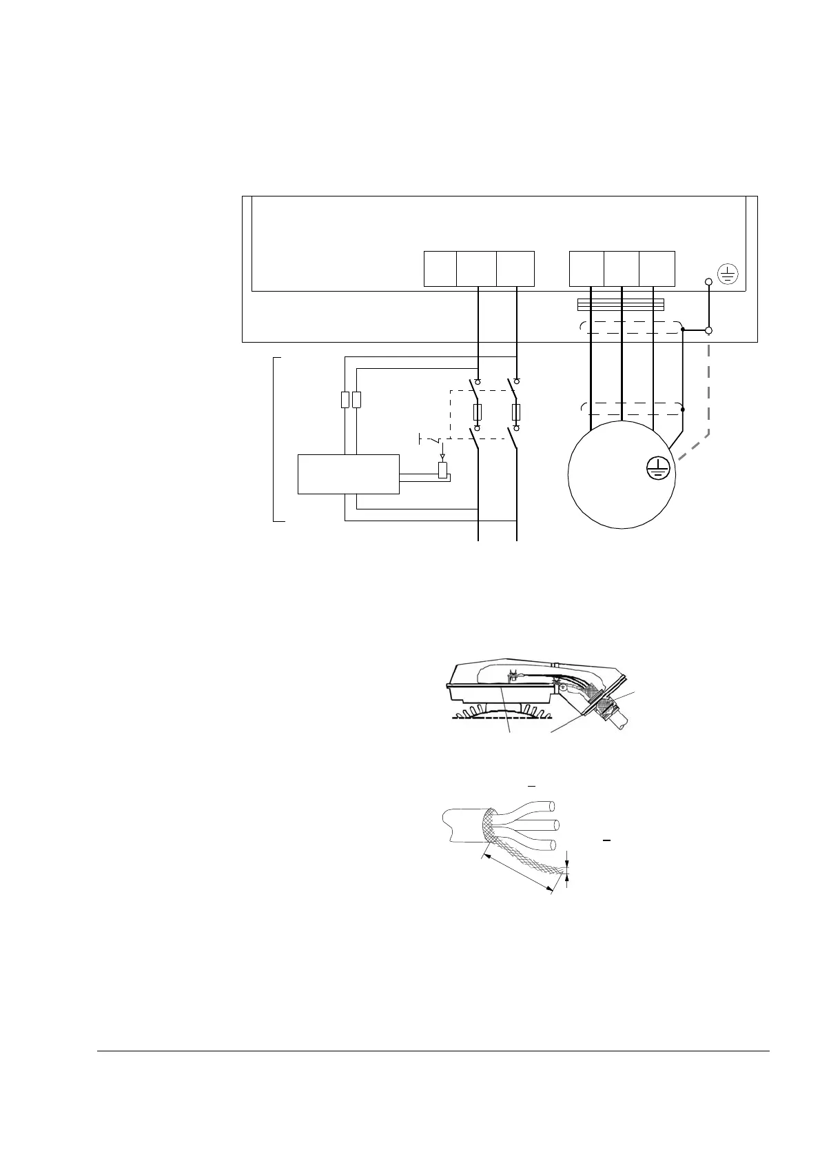
Diagram
Grounding of the motor cable shield at the motor end
For minimum radio frequency interference:
• ground the cable shield 360 degrees at the lead-through of
the motor terminal box
• or ground the cable by twisting the shield as follows:
flattened width >
1/5 × length.
360 degrees grounding
Conductive gaskets
a
b
b > 1/5 × a
*Use a separate grounding cable if the conductivity
of the cable shield is less than 50% of the
conductivity of the phase conductor in a cable with
no symmetrically constructed grounding conductor
(see the document ACS 800 MultiDrive; Planning
the Electrical Installation [3AFE 64783742,
English]).
Note:
If there is a symmetrically constructed grounding
conductor in the motor cable in addition to the
conductive shield, connect the grounding conductor
to the grounding terminal at the drive and motor
ends.
Do not use an asymmetrically constructed motor
cable. Connecting its fourth conductor at the motor
end increases bearing currents and causes extra
wear.
**Common mode filtering (optional)
INPUT
OUTPUT
U1
V1
W1
3~
Motor
UDC+
*)
Inverter module
UDC-
L+ L-
V2 W2U2
NCHM-01
Switch fuse controller
Note: Charging circuit
configuration may differ
from type to type. See the
chapter Circuit diagrams.
Cabinet
PE
**)
 Loading...


