Refer to the drawing below.
1.
Stop the drive and do the steps in section Electrical safety precautions (page 57) before
you start the work.
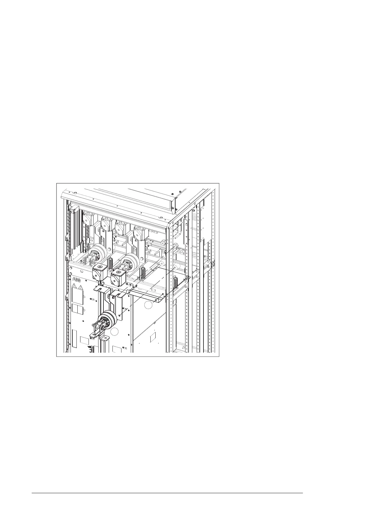
2. Remove the shrouding above the module bay (in front of the DC fuses).
3. Remove the DC fuses and the busbar assembly connecting the fuses to the inverter
module. Store these parts – they are to be reinstalled only with the inverter module.
Make note of the order of washers.
4. Remove the faulty module from its bay. See the module replacement instructions.
5. Install the air baffle (included) to the underside of the top module guide:
• Fasten the front edge of the baffle to the module mounting holes using the module
mounting screws (2 × M8). Tighten to 9 N·m (6.6 lbf·ft).
• Fasten the left/right sides of the baffle using M4 screws wherever possible. (This
depends on the location of the module in the cubicle.) Tighten to 1…2 N·m
(0.7 … 1.5 lbf·ft).
6. If the inverter control unit (A41) is powered from the faulty module, connect the power
supply wiring to another module using the extension wire set included.
7. If the Safe torque off (STO) function is in use, install the jumper wire set included in the
STO wiring in place of the missing module. (This is not needed if the module was the
last on the STO wire chain.)
8. Reinstall all shrouding removed earlier.
Note: Do not reinstall the DC fuses or busbars but store them elsewhere until the module
can be reinstalled.
9. Switch on the power to the drive.
10.
Enter the number of inverter modules present into parameter 95.13 Reduced run mode.
11. Reset all faults and start the drive.
12. If the Safe torque off (STO) function is in use, perform an acceptance test. See the STO
instructions.
124 Maintenance

 Loading...


