3. Push the module up the ramp and back into the cubicle.
• Keep your fingers away from the edge of the module front plate to avoid
pinching.
• Keep a constant pressure with one foot on the base of the module to prevent
the module from falling on its back.
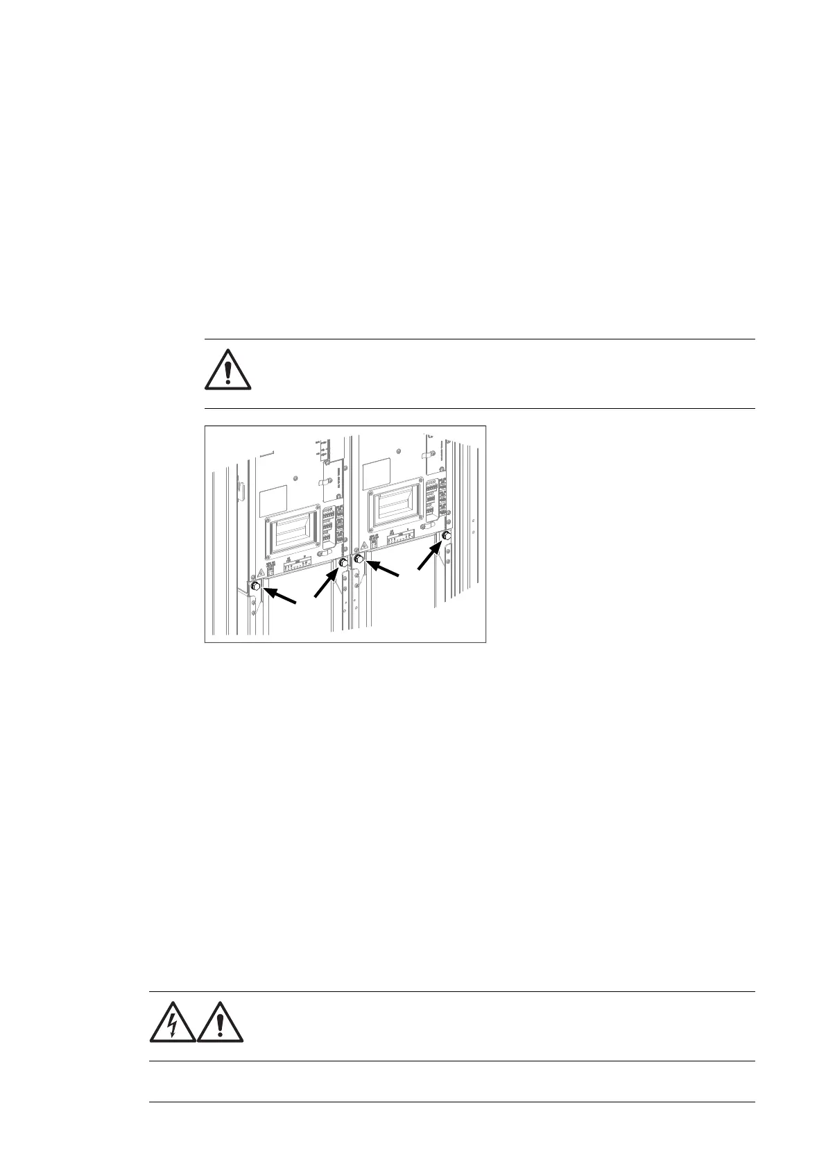
4. Secure the top front of the module with two screws. Tighten to 22 N·m (16 lbf·ft).
5. Secure the bottom front of the module with two screws. Tighten to 22 N·m (16 lbf·ft).
6. Remove the ramp.
7. Drives with option +C121 (Marine construction) or +C180 (Seismic design):
a. Remove the bolts holding the fan carriage (two bolts per module).
WARNING! The module retaining screws (two at top, two at bottom per
module) must be in place before removing these screws. Otherwise, the
parts of the module can become separated and cause injury or damage.
b. Reinstall the transverse retaining bracket. At the ends of the bracket, tighten the
screws to 9 N·m [6.6 lbf·ft]. Reinstall the fan carriage bolts removed at previous
step, and tighten to 22 N·m (16 lbf·ft).
8. Attach the DC busbars to the module. Tighten to 70 N·m (52 lbf·ft).
9. Reconnect terminal block [X50] at the top of the module.
10. Reconnect the wiring and fiber optic cables to the terminals on the front of the module.
11. Repeat the procedure for the other inverter modules.
12. Reinstall the shroud near the top of the cubicle.
Activating the reduced run of the inverter unit
A “reduced run” function is available for inverter units consisting of parallel-connected inverter
modules. The function makes it possible to continue operation with limited current even if
one (or more) module is out of service, for example, because of maintenance work. In
principle, reduced run is possible with only one module, but the physical requirements of
operating the motor still apply; for example, the modules remaining in use must be able to
provide the motor with enough magnetizing current.
WARNING!
Read the safety instructions. If you ignore them, injury or death, or damage
to the equipment can occur.
Maintenance 123

 Loading...


