Connecting the motor cable – Frame sizes R1i to R5i
■ Diagram
2)
1)
V2
W2
U2
2
3
1
4
X1
U1
V1
W1
3~
M
3)
1
2
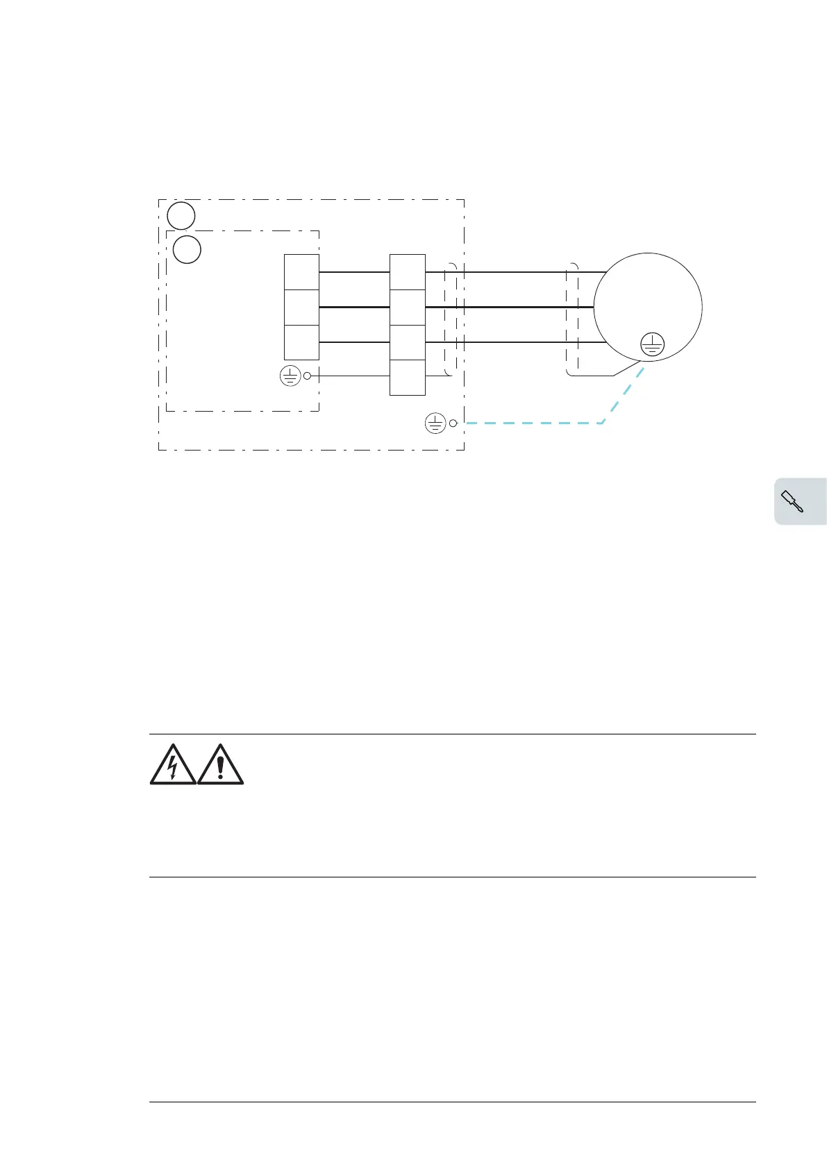
1. Inverter unit cubicle
2. Inverter module
1) 360° grounding at cable lead-through
2) Use a separate grounding cable if the conductivity of the cable shield is less than 50% of the conductivity
of the phase conductor in a cable with no symmetrically constructed grounding conductor (see the document
ACS880 multidrive cabinets and modules, Electrical planning instructions [3AUA00000102324, English]).
3) With frame R4i, terminal X1:4 may not be present if not required by the configuration (for example, output
filters). In this case, connect the cable shield directly to the PE busbar.
Note: If there is a symmetrically constructed grounding conductor in the motor cable in addition to the conductive
shield, connect the grounding conductor to the grounding terminal at the drive and motor ends.
Do not use an asymmetrically constructed motor cable. Connecting its fourth conductor at the motor end in-
creases bearing currents and causes extra wear.
■ Motor cable connection procedure
WARNING!
Read and follow the instructions given in Safety instructions for ACS880
multidrive cabinets and modules (3AUA0000102301 [English]). Ignoring
the instructions can cause physical injury or death, or damage to the
equipment. Refer to the diagram above. Also refer to the wiring diagrams
delivered with the unit for the component designations of the output
connectors.
1.
Do the steps in section Electrical safety precautions (page 57) before you start the work.
2. Run the cable into the cubicle through one of the cable glands provided. Remove the
outer jacket of the cable wherever it passes through the cable gland.
3. Cut the cable to suitable length and strip the ends of the individual conductors.
4. Twist the shield strands of the cable together to form a separate conductor and crimp
a ferrule onto it. (With frame R4i, connect the cable shield to the PE busbar using a
crimp ring terminal.)
5. Connect the conductors to terminal block/connector X1. (If X1:4 is not present, connect
the cable shield directly to the PE busbar.)
6. Secure the cable inside the cabinet mechanically.
Electrical installation 61

 Loading...


