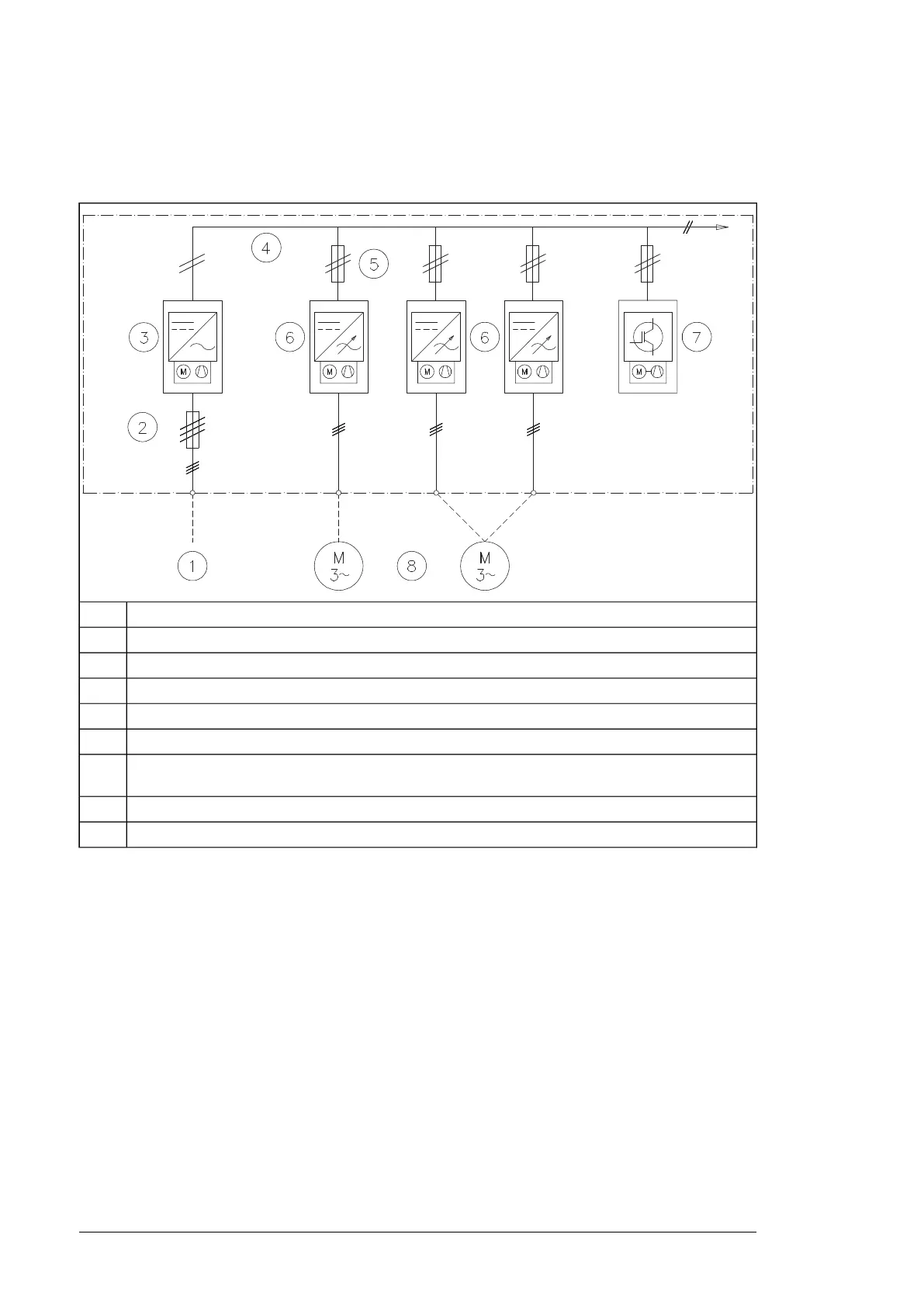
Overview diagram of the drive system
The diagram below depicts a common DC bus drive system.
DescriptionNo.
AC supply1
Input (AC) fuses2
Supply unit3
DC bus4
Inverter DC fuses (with or without a DC switch-disconnector)5
Inverter units (in this example, one of the two units consists of two inverter modules connected in par-
allel)
6
Brake unit (brake resistors not shown)7
Motor(s)8
The supply unit connects to the AC supply network and converts the AC voltage into DC.
The DC voltage is distributed through the DC bus to all inverter units. The inverter unit,
consisting of one or more inverter modules, converts the DC back to AC that rotates the
motor.
The inverter units can be used for controlling asynchronous AC induction motors, permanent
magnet synchronous motors, AC induction servomotors and ABB synchronous reluctance
motors (SynRM).
16 Hardware description

 Loading...


