Connecting the motor cables – Frame size R8i and multiples
without common motor terminal cubicle or sine output filter
On units without a common motor terminal cubicle or a sine output filter, the motor cables
connect to busbars located behind the inverter module(s). The location and dimensions of
the busbars are visible in the dimension drawings delivered with the drive, as well as the
example drawings presented in this manual in chapter Dimensions.
To allow the most room for the work, the modules can be removed completely from the
cabinet. For instructions, see section Removing the inverter module(s) (page 67).
Especially in the case of multiple inverter modules in the same cubicle, you can consider
only removing the fan carriage of each module. This is faster than removing the entire
module, but allows less room for the connecting work. For instructions, see section Removing
the fan carriage of an inverter module (page 71).
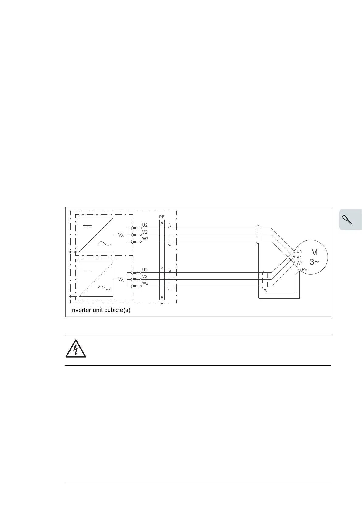
■ Motor connection diagram (without option +H366)
All parallel-connected inverter modules are to be cabled separately to the motor.
360° earthing is to be used at cable lead-throughs.
U2
V2
W2
PE
U2
V2
W2
M
3~
U1
W1
V1
PE
The recommended cable types are given in chapter Technical data.
WARNING!
The cabling from all inverter modules to the motor must be physically identical
considering cable type, cross-sectional area, and length.
Electrical installation 65

 Loading...


