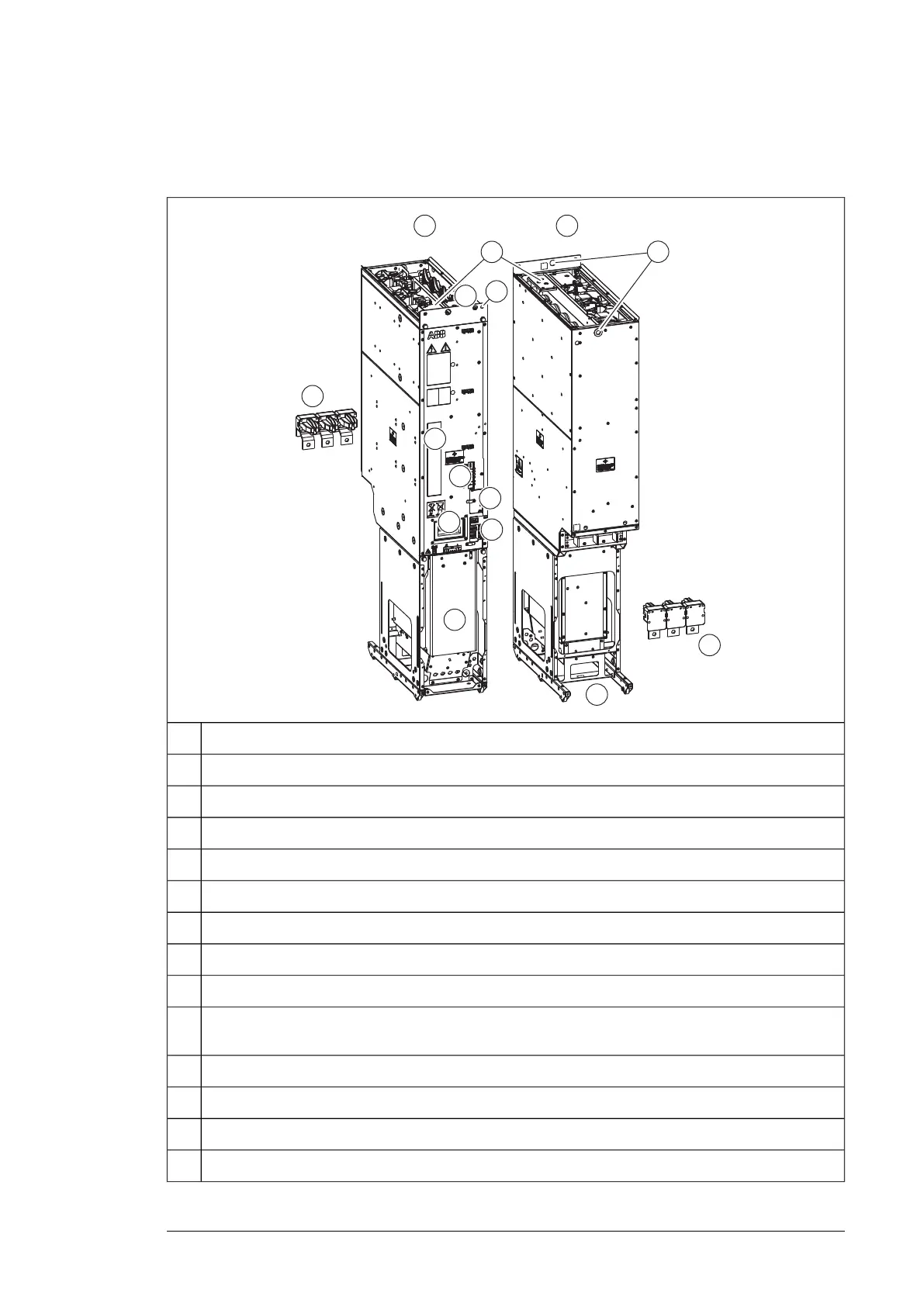
■ Inverter module frame size R8i and multiples
This figure shows the layout of the R8i module.
R8i module, frontA
R8i module, backB
DC busbars1
Handle2
LEDs and fiber optic connectors3
Fan (standard speed-controlled fan shown; a direct-on-line fan is available as option +C188)4
Quick connector (three phases). The counterpart is fastened to the cabinet behind the module.5
Wheels6
Type designation label7
Terminal block [X50] (power supply for internal boards and module heating element, option +C183; DOL
fan supply, option +C188)
8
Connectors [X51], [X52], [X53]9
The unpainted grounding point (PE) between module frame and cabinet frame.10
Lifting eyes11
Circuit board compartment fan12
Hardware description 27

 Loading...


