Re-installing the fan carriage of an inverter module
(If the inverter module was removed completely instead of only the fan carriage, proceed
to section Re-inserting the inverter modules into the cubicle (page 76)).
The re-installation of the fan carriage is the removal procedure in reverse. See section
Removing the fan carriage of an inverter module (page 71).
Re-inserting the inverter modules into the cubicle
WARNING!
Read the safety instructions given in Safety instructions for ACS880
multidrive cabinets and modules (3AUA0000102301 [English]). If you
ignore them, injury or death, or damage to the equipment can occur.
1. Make sure there are no tools, debris or any other foreign objects in the cubicle.
2. If not already in place, attach the module extraction/installation ramp (included) to the
base of the cabinet so that the tabs on the mounting bracket enter the slots on the ramp.
3. Push the module up the ramp and back into the cubicle.
• Keep your fingers away from the edge of the module front plate to avoid
pinching.
• Keep a constant pressure with one foot on the base of the module to prevent
the module from falling on its back.
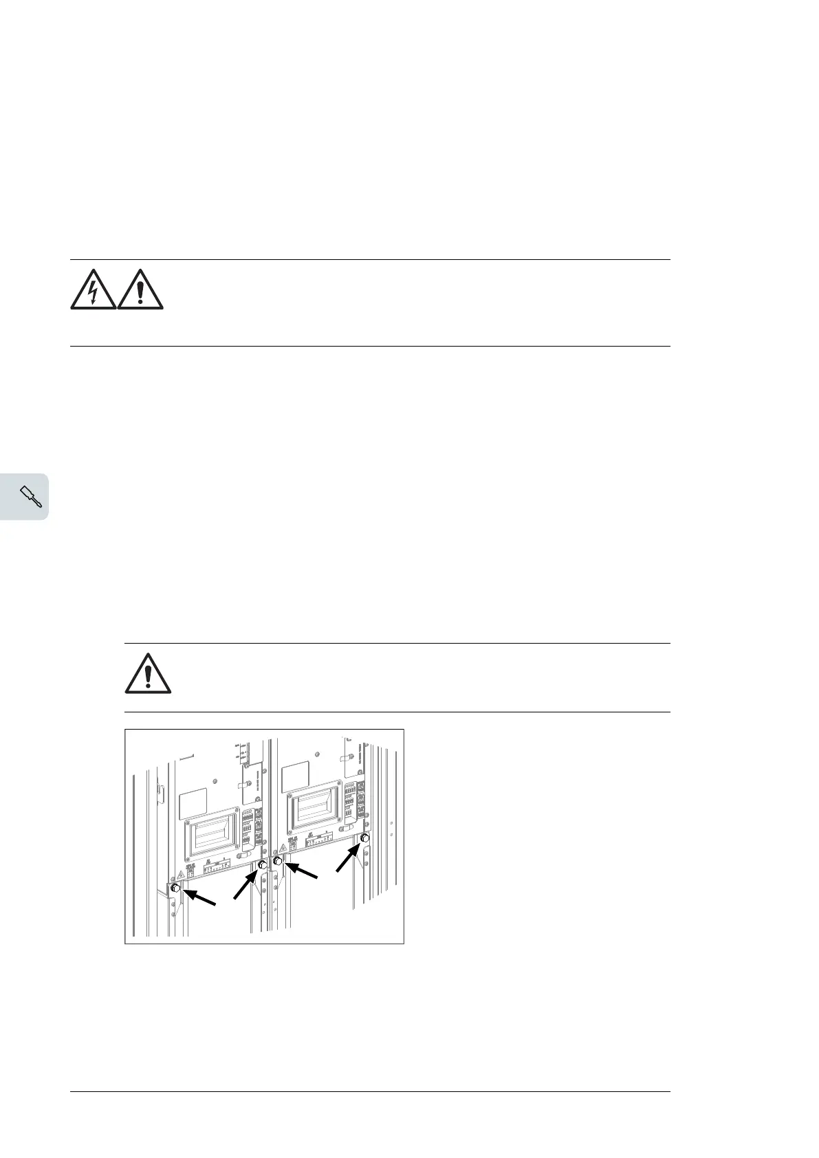
4. Secure the top front of the module with two screws. Tighten to 22 N·m (16 lbf·ft).
5. Secure the bottom front of the module with two screws. Tighten to 22 N·m (16 lbf·ft).
6. Remove the ramp.
7. Drives with option +C121 (Marine construction) or +C180 (Seismic design):
a. Remove the bolts holding the fan carriage (two bolts per module).
WARNING! The module retaining screws (two at top, two at bottom per
module) must be in place before removing these screws. Otherwise, the
parts of the module can become separated and cause injury or damage.
b. Reinstall the transverse retaining bracket. At the ends of the bracket, tighten the
screws to 9 N·m [6.6 lbf·ft]. Reinstall the fan carriage bolts removed at previous
step, and tighten to 22 N·m (16 lbf·ft).
8. Attach the DC busbars to the module. Tighten to 70 N·m (52 lbf·ft).
9. Reconnect terminal block [X50] at the top of the module.
76 Electrical installation

 Loading...


